ArduPilot Flying Wing Fixed-Wing Configuration Guide
I. Flight Principle Introduction
A flying wing is a fixed-wing aircraft without a traditional fuselage and tail surfaces, with all control surfaces located on the wing. Compared to traditional fixed-wing aircraft, the main characteristics of flying wings include:
- Higher aerodynamic efficiency: Reduces structural weight and increases endurance.
- Better maneuverability: More suitable for penetration and low-altitude flight.
- Different control method: Relies on Elevon (combined aileron + elevator) for pitch and roll control.
Since flying wings don't have traditional rudders, yaw control mainly relies on differential wing surface and automatic correction by the flight controller. In ArduPilot firmware, flying wings typically use Elevon mixing mode to achieve this type of control.

II. Equipment Preparation
Required Equipment:
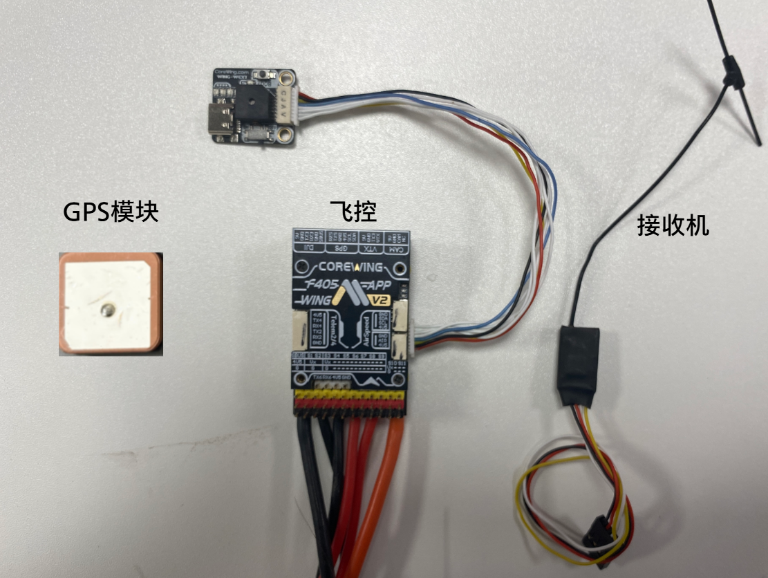
1) Flight Controller: CoreWing F405 WING V2 / CoreWing F405 WING MINI V2 - Any of these flight controllers are suitable for this tutorial.
2) RC Transmitter: Using RadioMaster Boxer / RadioMaster TX16S as examples.
3) Receiver: Using SpeedyBee ELRS Nano 2.4G RX as an example.
4) GPS Module: Using Beizheng BZ-251 GPS module as an example.
5) Motor: Using 2306 KV1950 motor, suitable for AIRWING, for reference only.
6) ESC: Using 35A~45A ESC, suitable for AIRWING, for reference only.
7) Servo: Using 9g metal digital servo, suitable for AIRWING, for reference only.
8) Battery: Using 4S1P 4000mah battery, suitable for AIRWING, for reference only.
9) Propeller: Using 7-inch three-blade or two-blade propeller, suitable for AIRWING, for reference only.
Optional Equipment:
1) Analog VTX: Using SpeedyBee TX 1600 VTX and RunCam Phoenix2 SE V2 camera as examples.
2) HD VTX: Using DJI O4 AIR UNIT VTX as an example.
3) Airspeed Sensor: Recommended to use digital airspeed sensor.

Important
Ground station installation can be referenced in this article: https://docs.corewing.com/plane/software/apsoftware/mp-version-install.html
Introduction to common functions and pages of Mission Planner can be referenced in this article: https://docs.corewing.com/plane/software/apsoftware/common-functions.html
How to update flight controller firmware - using Mission Planner ground control station: https://docs.corewing.com/plane/beforetuning/mp-fw-update.html
How to update flight controller firmware - using INAV ground control station: https://docs.corewing.com/plane/beforetuning/inav-fw-update.html
3. Initial Setup
3.1 Accelerometer Calibration
Important
Note: When calibrating the accelerometer, be sure to remove the flight controller from the aircraft and place it on a flat surface for calibration to improve accuracy and ensure stable flight!
- Connect the flight controller to the ground control station using a USB cable.
- Click Initial Setup.
- Click Accelerometer Calibration.
- Click Calibrate Accelerometer.
For detailed accelerometer calibration procedures, refer to:
Important
After completing the operation, disconnect the ground control station and all power to the flight controller, then reconnect the ground control station.

Important
During use, if there are significant temperature or climate changes, the gyroscope has suffered a severe impact, or the sensors have been replaced, the accelerometer needs to be recalibrated!
Important
For detailed accelerometer calibration procedures, refer to: https://docs.corewing.com/plane/ardupilot/settings/fc/accel-calibration.html
3.2 RC Transmitter Setup and Flight Mode Configuration
Important
Navigate to the MDL/MIXES page and check if the RC transmitter CH1-CH4 is set as follows. If not, modify the mixing.

3.2.1 Arming Channel Setup
1. RC Transmitter Setup
- Select a two-position switch
- Navigate to the
MDL/MIXESpage and configure its mixing asCH5

2. Ground Control Station Setup
- Enter Configuration/Debugging
- Enter All Parameters Table
- Search for
RC5_OPTION - Set the value of
RC5_OPTIONto153 - Click Write Parameters

Important
For detailed information on how to set arming and disarming, refer to this article: https://docs.corewing.com/plane/ardupilot/settings/fc/arming-disarm-setup.html
3.2.2 Return-to-Home Channel Setup
1. RC Transmitter Setup
- Select a two-position switch
- Navigate to the
MDL/MIXESpage and configure its mixing asCH6(settings may be adjusted based on actual conditions, for reference only)

2. Enable Return-to-Home Switch Setup
- Enter Configuration/Debugging
- Enter All Parameters Table
- Search for
RC6_OPTION - Set the value of
RC6_OPTIONto4 - Click Write Parameters

3.2.3 Flight Mode Setup
1. RC Transmitter Setup
- Select a three-position switch to set up a three-position flight mode switch
- Navigate to the
MDL/MIXESpage and configure its mixing asCH8

2. Ground Control Station Setup
Flight Mode Channel Setup:
- Enter Configuration/Debugging
- Enter All Parameters Table
- Search for
FLTMODE_CH - Set the value of
FLTMODE_CHto8(default is 8) - Click Write Parameters

Important
For detailed information on how to set up a six-position flight mode switch, refer to: https://docs.corewing.com/plane/ardupilot/settings/rc/sixpos-switch.html
Flight Mode Setup:
- Enter Initial Setup
- Enter Flight Modes
- Set the flight modes according to the diagram
- Click Save Modes

Important
For detailed information on flight modes, refer to this article: https://docs.corewing.com/plane/ardupilot/settings/fc/flight-modes.html
3.2.4 RC Transmitter Calibration
Important
Please bind the RC transmitter to the receiver before proceeding with the following steps.
For information on how to bind an ELRS receiver to the RC transmitter, refer to this article: https://docs.corewing.com/plane/ardupilot/settings/rc/elrs-bind.html
- Enter Initial Setup.
- Enter RC Transmitter Calibration.
- Click Calibrate Transmitter.
- Note: Check the box for PITCH reversal.

Important
For detailed RC transmitter calibration procedures, refer to: https://docs.corewing.com/plane/ardupilot/settings/fc/calibration.html
4. Equipment Installation
4.1 Flight Controller Wiring
- Power Wiring
Important
Note:
The positive power lead must be connected to the designated pad.
ESC refers to the Electronic Speed Controller.
When soldering, ensure there are no cold joints.

4.2 Flight Controller Mounting
Important
The standard orientation for the flight controller should align with the aircraft's nose direction, but on this aircraft, it's not convenient to install in that orientation, so the mounting orientation needs to be changed.
If you need to adjust other mounting orientations for the flight controller, refer to this article for setup: https://docs.corewing.com/plane/ardupilot/settings/fc/orientation-setup.html
The flight controller should be mounted at the aircraft's center of gravity. Refer to the image below for installation:

Parameters need to be adjusted according to the installation orientation shown above:

4.3 Peripheral Installation and Setup
- Peripheral Wiring

4.3.1 Receiver Installation and Setup
The installation position is shown in the figure. Route the antenna outside the fuselage and secure it with tape:

Set up RSSI_TYPE:
- Enter Configuration/Tuning
- Enter All Parameters Table
- Search for
RSSI_TYPE - Set the value of
RSSI_TYPEto3 - Click Write Parameters

4.3.2 Servo Output Setup (Servo and Motor Configuration) and Control Surface Check
Important
The flight controller has its own BEC (Battery Eliminator Circuit). If the ESC also has a BEC, you must remove the middle power wire and insulate it properly to prevent it from contacting conductors during flight, which could cause a short circuit!
Output Wiring:

Parameter Setup:
- Enter Initial Setup
- Enter Servo Output
- Configure Outputs
| Channel | Output | Description |
|---|---|---|
| S1 | ElevonLeft | Left Elevon |
| S2 | ElevonRight | Right Elevon |
| S3 | Throttle | Throttle |

Important
Note:
The minimum and midpoint values for throttle are the same. When changing outputs in Mission Planner, it does not automatically update the throttle midpoint value, so please check this carefully.
Configure outputs according to timer groups as much as possible, placing similar devices in the same group. For timer group information, refer to the flight controller manual "Part5-Pin Mapping-ArduPilot Pin Mapping" section.
Control Surface Check:
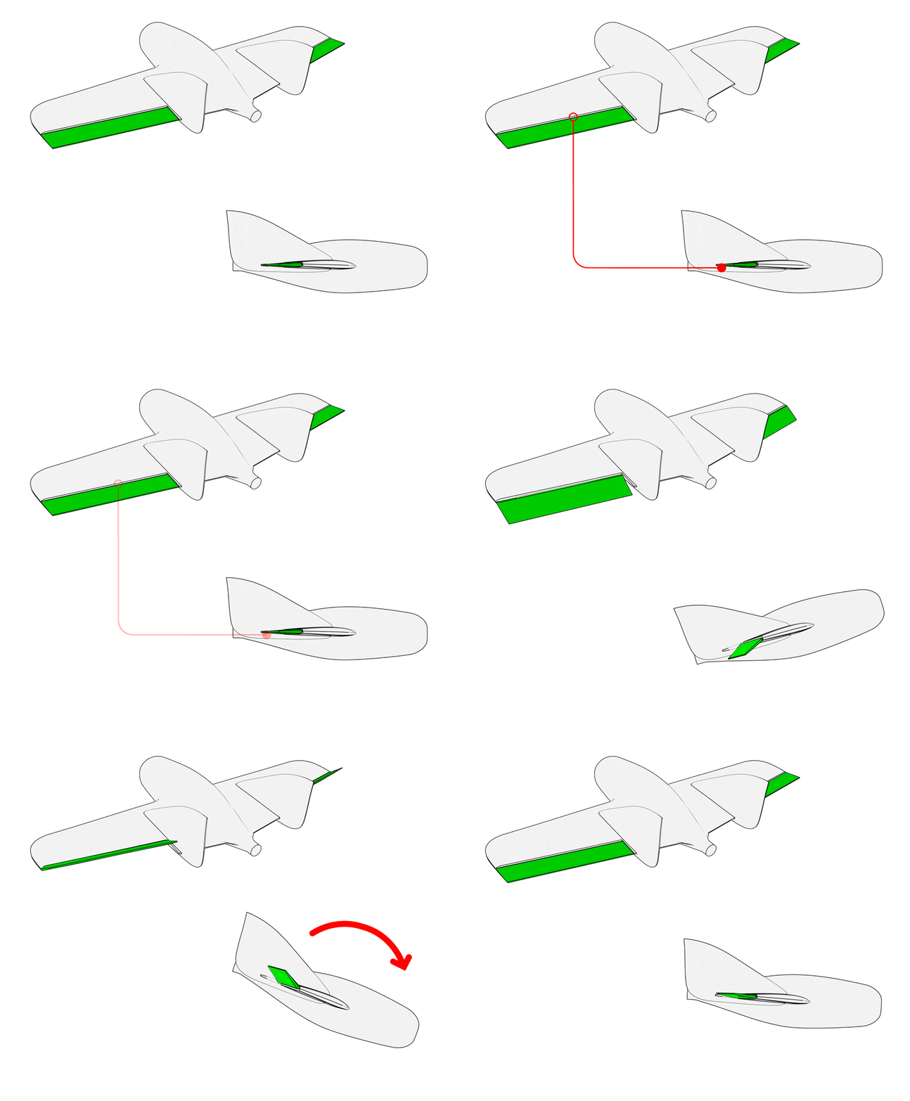
a. Control surface feedback check in Stabilize mode
Important
Switch the flight mode to FBWA Mode
- When the aircraft rolls left, the left wing control surface deflects down, and the right wing control surface deflects up.
- When the aircraft rolls right, the left wing control surface deflects up, and the right wing control surface deflects down.
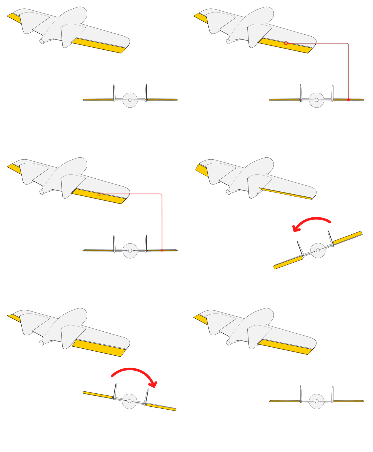
- When the aircraft pitches up, both control surfaces deflect down.
- When the aircraft pitches down, both control surfaces deflect up.
b. Control surface feedback check in Manual mode
Important
Switch the flight mode to ACRO Mode
- When moving the aileron stick left, the left wing control surface deflects up, and the right wing control surface deflects down.
- When moving the aileron stick right, the left wing control surface deflects down, and the right wing control surface deflects up.
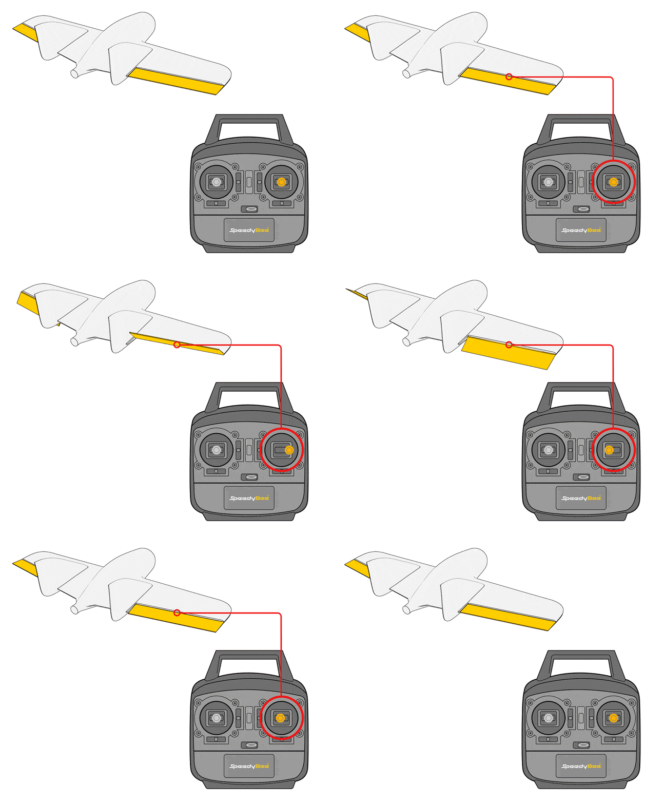
- When moving the elevator stick up, both control surfaces deflect down.
- When moving the elevator stick down, both control surfaces deflect up.
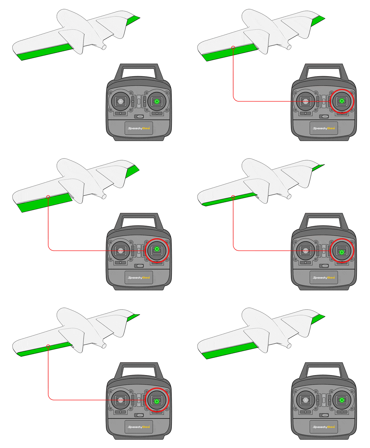
Check the Stabilize mode feedback first, then check the Manual mode feedback. If the Stabilize mode feedback is incorrect, simply reverse the incorrect control surface channel.

Important
For detailed information on how to confirm if the control surface feedback is correct, refer to this article: https://docs.corewing.com/plane/ardupilot/settings/fc/dir-check.html
4.3.3 GPS Module Installation
The installation position is shown in the figure. Secure the module to the bottom with 3M adhesive. Ensure the module is mounted securely, as this will significantly affect flight performance:
Important
When installing, ensure it is mounted horizontally and vertically without tilting, otherwise the installation angle cannot be set correctly.

Important
Install away from metal components such as magnetic compartment covers, metal pushrods, etc., as this will interfere with the compass.
Install away from receivers, servo wires, motors, and other devices, as this will interfere with the compass.
Confirm that the installation is secure.
For detailed installation procedures for different modules, refer to their respective manuals.
4.3.4 Video Transmitter Installation and OSD Setup
- Analog Video Transmitter Installation:

- Analog Video Transmitter Parameter Setup:


Important
For detailed information on analog video transmitter parameter setup, refer to this article: https://docs.corewing.com/plane/ardupilot/settings/vtx/analog-vtx/config.html
- HD Video Transmitter Installation:

- HD Video Transmitter Parameter Setup:


Important
For detailed information on HD video transmitter parameter setup, refer to this article: https://docs.corewing.com/plane/ardupilot/settings/vtx/hd-vtx/config.html
OSD Setup:
OSD configuration file: osd.param, which can be downloaded and imported directly.
Enter Configuration/Tuning.
Enter All Parameters Table.
Click Load.
Select the OSD parameter file.
Click Open.
Click Write Parameters.

- OSD display effect as follows:

Important
For detailed information on how to set up OSD elements, refer to this article: https://docs.corewing.com/plane/ardupilot/settings/fc/osd.html
4.3.5 Airspeed Sensor Installation and Setup
Refer to the following for airspeed sensor installation position:

Important
For detailed information on airspeed sensor installation, parameter setup, and calibration, refer to this article: https://docs.corewing.com/plane/ardupilot/settings/airspeed/airspeed-setup.html
V. Pre-flight Tuning
5.1 ESC Calibration
Important
Ensure the battery is disconnected, the receiver is bound, and propellers are removed! Switch the flight mode to Manual Mode
① Click Flight Data → Click Actions → Click Arm/Disarm → Click Force Arm.

② Immediately push the throttle to the highest position.
③ Power the flight controller with the battery.
④ The ESC will make a sound → immediately push the throttle to the lowest position → the ESC sound will end.
BLHeli32/BLHeli_S ESC Calibration Sounds:
Connect the battery and wait 2 seconds → "Play a song" is the throttle highest point confirmation sound → Wait for the song to finish → Push the throttle to the lowest position and wait 1 second → "Play another song, dee-dee-" is the throttle lowest point confirmation sound → Calibration complete
PWM ESC Calibration Sounds.
Connect the battery and wait 2 seconds → "Beep-beep" is the throttle highest point confirmation sound → Push the throttle to the lowest position and wait 1 second, N beeps indicate the number of LiPo cells → "Beep" is the throttle lowest point confirmation sound → Calibration complete.
⑤ Gently push the throttle, the motors will start rotating immediately. Push the throttle from 0% to 20% and check if the throttle response is linear.
⑥ If the result differs from the above, disconnect the battery and return to step ② to recalibrate.
Important
For detailed information on ESC calibration and Dshot protocol activation, refer to this article: https://docs.corewing.com/plane/ardupilot/settings/esc/esc-dshot.html
5.2 Motor Direction Check and Propeller Installation
- Choose regular or reverse propellers according to motor rotation direction
- When installing propellers, note that the side with text should face the nose

To counteract motor torque, you can adjust the control surfaces using the following methods:

5.3 Compass Calibration
- Enter Initial Setup.
- Click Compass.
- Check if module information is displayed; if not, check the wiring and module.
- Check Use Compass 1.
- Click Start to begin compass calibration.
- Tilt and rotate the aircraft to fill the progress bar.
- After the popup appears, click OK.
- Click Reboot, the flight controller will restart automatically.
Important
Stay away from metal objects during calibration, such as cars, electric vehicles, high-voltage power towers;
Calibrate outdoors with good GPS signal (at least 8 satellites);
During calibration, try to use wireless tuning to avoid USB cable interference;
If GPS/compass module is replaced or flight controller position is adjusted, recalibration is required.


Important
Compass calibration must be accurate, otherwise it will cause ground control station errors: EK3 active/DCM active
Important
For detailed information on compass calibration, refer to this article: https://docs.corewing.com/plane/ardupilot/settings/gps/ap-compass-setup.html
5.4 Level Calibration
Important
After the flight controller is installed, a level calibration must be performed to compensate for the installation angle of the gyroscope and determine the correct level flight attitude!
- Place the aircraft flat on a level surface to perform level calibration.


5.5 Loss of Control Protection Parameter Settings
Important
For detailed information on how to set loss of control protection parameters, refer to this article: https://docs.corewing.com/plane/ardupilot/settings/fc/failsafe.html
6. Flight Test
6.1 Pre-flight Check Parameter Settings
Enter Configuration/Tuning.
Enter All Parameters.
Search
ARMING_CHECK.Set the required unlocked check items.

Important
For detailed information on how to set unlocked check parameters, refer to this article: https://docs.corewing.com/plane/ardupilot/settings/fc/prearm-check-setup.html
6.2 Pre-flight Inspection
6.2.1 Center of Gravity Check
1. Reference aircraft markings:
- Many flying wing or fixed-wing aircraft have recommended center of gravity positions marked, typically at 25-30% behind the main wing leading edge.

2. Finger support method:
- Place the aircraft on two fingers at the recommended center of gravity point under the main wing, and gently balance the fuselage.
- If the nose is too heavy or the tail is too heavy, adjust the battery or add ballast.
Nose heavy (center of gravity too far forward):
- The aircraft will have difficulty climbing during flight, which may cause takeoff failure and crash.
- Try moving the battery backward or reducing nose ballast.
Tail heavy (center of gravity too far back):
- The aircraft is prone to stall when pitching up.
- Solution: Move the battery forward or add nose ballast.
6.2.2 Pre-flight Control Surface Check
Important
Switch flight mode to FBWA Mode
When the aircraft rolls left, the left wing control surface deflects down, and the right wing control surface deflects up.
When the aircraft rolls right, the left wing control surface deflects up, and the right wing control surface deflects down.
When the aircraft pitches up, both control surfaces deflect down.
When the aircraft pitches down, both control surfaces deflect up.
Important
Switch flight mode to ACRO Mode
When the aileron stick is moved left, the left wing control surface deflects up, and the right wing control surface deflects down.
When the aileron stick is moved right, the left wing control surface deflects down, and the right wing control surface deflects up.
When the elevator stick is moved up, both control surfaces deflect down.
When the elevator stick is moved down, both control surfaces deflect up.
6.2.3 Satellite Number Check
Important
Outdoors, check if the satellite count is greater than 8. Only take off if it's greater than 8!
If the satellite count remains below 8, move to an open area. If there's no improvement, replace the GPS module.

6.2.4 Wind Direction Confirmation
Observe wind direction:
- Observe wind indicators such as smoke, windsocks, flags.
- Use light objects (like grass leaves) and throw them into the air to observe the direction they drift.
Determine upwind takeoff direction:
- Taking off into the wind provides more lift and reduces the required takeoff speed.
- Taking off with the wind may cause stalling or the nose being pushed down by the wind, easily leading to a crash.
6.3 Takeoff Instructions
Depending on the aircraft configuration, choose hand-launch takeoff or runway takeoff to ensure a successful takeoff.
6.3.1 Hand-launch Takeoff
1. Mode preparation:
- Select
ACRO Modeto ensure sufficient control surface deflection. - Throttle to 60-80% to ensure sufficient takeoff thrust.
2. Takeoff posture:
- Hold under the wings. For flying wings, hold the wings to prevent hand injury.
- Launch at a 30° upward angle to ensure sufficient lift.
3. Launch technique:
- Use moderate force, avoiding too strong or too light (insufficient for climbing).
- Follow through with the motion, rather than throwing downward.
Important
Precautions:
Avoid launching with low throttle. Ensure sufficient takeoff power. Immediately take control of the aileron after launching to prevent uncontrolled roll.
6.3.2 Runway Takeoff
- Select
ACRO Mode. - Throttle to 60%-70% to maintain moderate acceleration.
- Maintain directional stability to prevent uncontrolled yaw during taxiing.
- When the aircraft reaches sufficient speed, gently pull up the pitch for a smooth takeoff.
Important
Precautions:
Ensure sufficient takeoff distance to avoid stalling from rapid ascent in a short distance.
Takeoff into the wind to increase lift, avoid crosswind effects.
Monitor flight status to prevent excessive pitch-up or rapid banking.
6.4 In-flight Testing
Important
Case study
- During flight, the aircraft's flight attitude was not confirmed to match the flight angle of attack, resulting in a nose-down condition during autonomous flight. At the same time, auto-tuning was not performed, and the PID was insufficient, causing the aircraft to be unable to generate sufficient control surface deflection for adequate control response. When switching to RTL mode, the aircraft entered autonomous flight and immediately accelerated into a dive, crashing into the ground!
First-person flight view:
Third-person flight view:Therefore, conducting a complete in-flight test is essential.
1. OSD Settings
- Enter Configuration/Tuning
- Enter the Onboard OSD page
- Check Roll (ROLL)
- Check Pitch (PITCH)
- Write to flight controller

2. Control Surface Test
- After successful takeoff, switch the flight mode to
FBWA Modeto see if the aircraft automatically corrects its attitude.
Important
If the aircraft's attitude is abnormal, switch to ACRO Mode Land and check the control surfaces under FBWA Mode.
3. Level Flight Test and Adjustment
Important
You can determine if the aircraft is pitching up or down by observing the attitude indicator on the OSD!

- Switch to
CRUISE Modeand fly once downwind and once upwind, observing the OSD attitude indicator, paying attention to the pitch and roll change angles. - If the roll change angle exceeds 3°-5°, switch to
FBWA Modeto land promptly and re-perform level calibration.

- If the pitch change angle exceeds 3°-5°, switch to
FBWA Modeto land and adjust the value ofPTCH_TRIM_DEGto make the aircraft maintain level flight at the flight angle of attack.

- If the aircraft pitches down during level flight, increase the value of
PTCH_TRIM_DEGto a positive value. - If the aircraft pitches up during level flight, decrease the value of
PTCH_TRIM_DEGto a negative value.

4. Perform SERVO_AUTO_TRIM (Servo Auto-trim)
- Take off, perform tuning with
SERVO_AUTO_TRIM, and land after tuning is complete.
Important
For information on how to perform SERVO_AUTO_TRIM (Servo Auto-trim), refer to this article: https://docs.corewing.com/plane/ardupilot/settings/fc/servo-autotrim.html
5. Auto-tuning
- Take off, switch the flight mode to
AUTOTUNE Modeto perform auto-tuning, and land after tuning is complete.
Important
For detailed information on how to use auto-tuning, refer to this article: https://docs.corewing.com/plane/ardupilot/settings/fc/autotune.html
6. Throttle Optimization
- Take off, switch to
CRUISE Mode, and fly into the wind to check if the current cruise throttle setting allows the aircraft to maintain level flight. If the aircraft pitches up or down, adjust the cruise throttle. Increase throttle if the nose drops, decrease throttle if the nose rises. - Then take off again, switch to
CRUISE Mode, and fly into the wind to confirm if the current cruise throttle is appropriate. At the same time, observe the ground speed displayed on the OSD and record it as [Cruise Speed].

- Switch to FBWA mode, maintain the throttle at cruise throttle, and fly downwind. Observe the ground speed displayed on the OSD and record it as [Downwind Ground Speed].
- Stay in FBWA mode, maintain the throttle at cruise throttle, and fly into the wind. Observe the ground speed displayed on the OSD and record it as [Upwind Ground Speed].
- [Downwind Ground Speed] ÷ 3.6 =
[AIRSPEED_MAX], [Upwind Ground Speed] ÷ 3.6 =[AIRSPEED_MIN], round the results and enter them inAIRSPEED_MAXandAIRSPEED_MINrespectively.

- [Cruise Speed] ÷ 3.6 =
[AIRSPEED_CRUISE], ensure[AIRSPEED_CRUISE]is slightly greater than[AIRSPEED_MIN], round the result and enter it inAIRSPEED_CRUISE.

7. Flight Data Check
- Observe data in Mission Planner or
OSDto confirm that GPS, heading, altitude, ground speed, voltage, current and other data are normal.
Important
If abnormal data is detected, land promptly and check the equipment!
8. Return-to-Home (RTH) Function Test
- Switch the flight mode to
RTL Modeto test if the aircraft returns to the takeoff unlock point and circles around it.
Important
If the flight attitude is abnormal in RTH mode, promptly switch to ACRO or FBWA and check the RTH parameter settings!
9. Pre-landing Check:
- Confirm battery remaining capacity to ensure sufficient power for landing.
- Observe wind direction and choose an upwind landing direction.
Technical Support QR Code