ZOHD ALTUS VTOL (PNP) Quick Start Guide - ArduPilot
ZOHD ALTUS Parameters:
CoreWing F405 WING V2 Parameters:
ZOHD ALTUS_Y3 VTOL Parameters CoreWing_F405_WING_V2.param
CoreWing F405 WING MINI V2 Parameters:
ZOHD ALTUS_Y3 VTOL Parameters CoreWing_F405_WING_MINI_V2.param
SpeedyBee F405 WING APP / MINI Parameters:
ZOHD ALTUS_Y3 VTOL Parameters SpeedyBee_F405_WING_APP_MINI.param
MissionPlanner Ground Control Station (GCS) Introduction: Click to jump to link
Firmware Flashing Tutorial (This tutorial uses AP4.5.7 firmware): Click to jump to link
Follow the tutorial below for assembly to achieve the best results with the parameters
1. Basic Principles of VTOL Fixed-Wing UAVs
VTOL fixed-wing UAVs combine multi-rotor and fixed-wing technologies, using multi-rotors for vertical take-off and landing, and switching to fixed-wing mode through a transition mechanism to achieve efficient horizontal flight. In horizontal flight, lift is generated by the wings, and direction and attitude are adjusted via control surfaces.
2. Pre-Assembly Preparation
1. PNP Kit:
It is recommended to use soft-pack batteries with a high discharge rate, and the batteries should be in good health with few usage cycles.
2. Electronic Equipment:
The ZOHD ALTUS flight controller parameters are configured and tested based on the assembly with the following equipment. The essential equipment determines the actual effectiveness of the recommended parameters.
A. Essential Equipment:
Flight Controller (FC): CoreWing F405 WING V2 /CoreWing F405 WING MINI V2
Compass: Beizheng BZ-251GPS M10 Compass 5883
Receiver: SpeedyBee Nano 2.4G ELRS Receiver
Airspeed Sensor: Digital Airspeed Sensor
B. Optional Equipment:
Analog VTX:
VTX Module: SpeedyBee TX ULTRA 1.6W
Camera: RunCam Phoenix 2 SE V2
HD VTX: DJI O4 AIR UNIT
2.1 Accelerometer Calibration
Important
Note: When performing accelerometer calibration, be sure to remove the flight controller from the fuselage and calibrate it on a flat desktop to improve calibration accuracy and ensure flight stability!
- Use a USB data cable to connect the flight controller to the ground control station (GCS).
- Click Initial Setup.
- Click Accelerometer Calibration.
- Click Calibrate Accelerometer.
For the specific operation process of accelerometer calibration, please refer to:
Important
After completing the operation, disconnect the GCS and all power to the flight controller, then reconnect to the GCS.

Important
If there are significant temperature and climate changes during use, the gyroscope suffers a severe impact, or the sensor is replaced, the accelerometer must be recalibrated!
Important
For detailed operation process of accelerometer calibration, please refer to: https://docs.corewing.com/plane/ardupilot/settings/fc/accel-calibration.html
2.2 Importing Parameters
A. Enable VTOL Parameters
- Click Config/Tuning
- Click Full Parameter List
- Search for Q_ENABLE
- Set the value of Q_ENABLE to 1
- Click Write Params (click twice, a popup will prompt Saved)

Important
After completing the operation, disconnect the GCS and all power to the flight controller, then reconnect to the GCS.
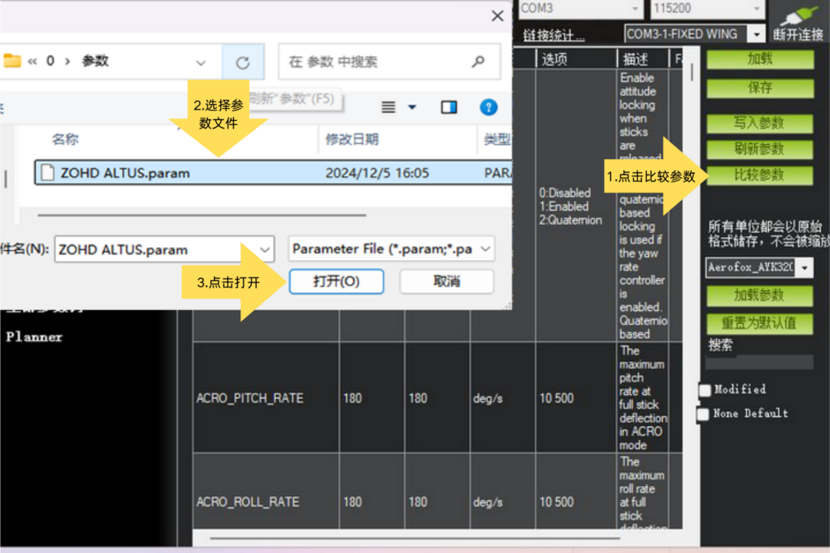
B. Import Parameters
- Click Compare Params
- Select Parameter File
- Click Open
- Click continue
- Click OK or yes if prompted
- Click Write Params, wait for the popup to prompt Saved
- Repeat until there are no parameter differences in Param Compare

Important
After each operation, disconnect the GCS and all power to the flight controller, reconnect to the GCS, and return to the first step to repeat the operation until there are no parameter differences in the Compare Params interface.
2.3 PNP Kit Inspection
A. Check the kit for any damage and ensure it is securely assembled.
B. Switch the servo tester to the middle position, check if the control surfaces are flush, and adjust the pushrods if they are not. Connect the tilt servo, switch to Auto mode or manually adjust the knob to test whether the tilt servo rotates smoothly.
Important
Note: When using the servo tester, do not rotate the servo to its maximum angle, as this can easily damage the servo.
If a servo tester is not available, a PWM receiver can be used instead.

C. The PNP kit has already categorized most of the wires, but it is recommended to verify them all with a servo tester to prevent wiring errors during assembly.
3. Equipment Assembly
Complete the assembly of the PNP kit before proceeding with the following operations:
3.1 Flight Controller Wiring
The flight controller power wiring is shown in the figure:
The wiring between the flight controller and peripherals is shown in the figure:
3.2 Flight Controller Installation
The flight controller should be installed at the center of gravity of the aircraft and the center position of the three motors. Install it according to the figure below.
The SERVO OUTPUT parameter settings are shown in the figure:
The flight controller pin header wiring is shown in the figure:
3.3 Receiver Installation

3.4 GPS Module Installation
The installation position is shown in the figure. Use 3M tape to fix the bottom of the module, ensure the module is securely installed, otherwise it will significantly affect flight performance:
Important
- Install away from metal objects, such as magnetic hatch covers, metal pushrods, etc., otherwise the compass will be interfered with.
- Install away from receivers, servo wires, motors, and other equipment, otherwise the compass will be interfered with.
- Make sure to confirm that the installation is secure.
- For detailed installation operations of different modules, please refer to their respective manuals.
3.5 Pitot Tube Installation
You can refer to the following pitot tube installation position for installation, fix it with 3M tape. It is best to place the airspeed sensor inside the fuselage for better performance:

3.6 RC Transmitter Calibration and Channel Mixing Configuration
Important
You can refer to this article: https://docs.corewing.com/plane/ardupilot/settings/fc/calibration.html
4. Flight Mode Introduction
The following seven flight modes will be used: ACRO, Manual, STABILIZE, FBWA, QSTABILIZE, QLOITER, QHOVER.
Important
For detailed descriptions of flight modes, please refer to: https://docs.corewing.com/plane/ardupilot/settings/fc/flight-modes.html
5. Aircraft Debugging
Perform aircraft debugging after installing the electronic equipment:
5.1 VTOL Mode Check
Set the three-position flight mode to QSTABILIZE, STABILIZE, Manual
5.1.1 Tilt Servo Check
Important
Do not install propellers during testing!
Switch the flight mode to QSTABILIZE, and connect the battery for power;
The tilt servo is vertically at 90 degrees in VTOL mode, as shown in the figure:
If not, adjust the min value of channel 8 and the max value of channel 9, as shown in the figure:
Switch the flight mode to Manual;
The tilt servo is horizontally at 180 degrees in fixed-wing mode, as shown in the figure below:
If not, adjust the max value of channel 8 and the min value of channel 9, as shown in the figure:
5.1.2 ESC Calibration
Important
Ensure the battery is disconnected, the receiver is bound, and propellers are removed! Switch the flight mode to QACRO mode
① Click Flight Data → click Actions → click Arm/Disarm → click Force Arm.
② Immediately push the throttle to the maximum.
③ Power the flight controller (FC) with the battery.
④ The ESC plays a prompt tone → immediately push the throttle to the minimum → the ESC prompt tone ends.
BLHeli32/BLHeli_S ESC Calibration Tones:
Connect the battery and wait for 2 seconds → "plays a musical tone" as the throttle maximum confirmation tone → wait for the music to finish playing → push the throttle to the minimum and wait for 1 second → "plays another musical tone, beep-beep-" as the throttle minimum confirmation tone → calibration complete
PWM ESC Calibration Tones:
Connect the battery and wait for 2 seconds → "beep-beep-" throttle maximum confirmation tone → push the throttle to the minimum and wait for 1 second, N short beeps indicating the number of LiPo battery cells → "beep-" throttle minimum confirmation tone → calibration complete.
⑤ Gently push the throttle, and the motors should spin immediately. Push the throttle from 0% to 20% to check if the throttle response is linear.
⑥ If the result differs from the above, disconnect the battery and return to step ② to recalibrate.
Important
For detailed information on ESC calibration and enabling the Dshot protocol, please refer to this article: https://docs.corewing.com/plane/ardupilot/settings/esc/esc-dshot.html
5.1.3 Motor Rotation Direction Check
Important
Do not install propellers during testing!
Force arm the aircraft, and check the rotation direction of each motor:
Gently push the throttle. The correct motor rotation directions are: left motor counterclockwise, right motor clockwise, and tail motor counterclockwise, as shown in the figure below. You can lightly touch the motor to feel the rotation direction:
Important
If the motor rotation direction is incorrect, swap any two of the three motor wires of the respective motor to reverse the direction.
5.1.4 RC Transmitter Output Check
Force arm → gently push the throttle until the motors just start spinning → all motors are spinning → lightly move the sticks to give commands to the flight controller (FC).
Important
Motor speed can be felt by attaching tape or masking tape to the motor.
- Push the pitch stick, tail motor speed increases;
- Pull the pitch stick, left-front and right-front motor speeds increase;
- Apply left roll, right-front motor speed increases;
- Apply right roll, left-front motor speed increases;
If the feedback is inconsistent, please check the SERVO OUTPUT and pin header wiring.
5.1.5 Motor Self-Stabilization Feedback Check
Force arm → gently push the throttle until the motors just start spinning → all motors are spinning → give the aircraft a certain attitude change.
Important
Motor speed can be felt by attaching tape or masking tape to the motor.
- When the aircraft pitches up, tail motor speed increases;

- When the aircraft pitches down, left-front and right-front motor speeds increase;

- When the aircraft rolls left, left-front motor speed increases;

- When the aircraft rolls right, right-front motor speed increases;

If the motor feedback is inconsistent with the above, please check the SERVO OUTPUT and pin header wiring.
5.1.6 Propeller Installation
- Select CW or CCW propellers based on the motor rotation direction.
- When installing propellers, ensure the side with text is facing up.

5.2 Fixed-Wing Check
Important
For control surface checks, please refer to: https://docs.corewing.com/plane/ardupilot/settings/fc/dir-check.html
Check in STABILIZE mode whether the control surface feedback is correct when giving the aircraft attitude changes. If incorrect, please check SERVO OUTPUT.
Check in Manual mode whether the control surface feedback is correct when moving the RC sticks. If incorrect, please check RC transmitter calibration.
5.3 Compass Calibration
- Enter Initial Setup.
- Click Compass.
- Check if module-related information is displayed. If not, please check the connection cables and the module.
- Check Use Compass 1.
- Click Start to begin compass calibration.
- Move the aircraft until the progress bar is full.
- Click OK after the pop-up appears.
- Click Reboot, and the flight controller (FC) will restart automatically.
Important
Stay away from metal objects during calibration, such as cars, electric vehicles, and high-voltage towers;
Calibrate outdoors when GPS signal is good (at least 8 satellites);
Use wireless tuning during calibration if possible to avoid USB cable interference;
If the GPS/compass module is replaced or the flight controller (FC) installation position is changed, recalibration is required.


Important
For detailed information on compass calibration, please refer to this article: https://docs.corewing.com/plane/ardupilot/settings/gps/ap-compass-setup.html
5.4 Level Calibration
Important
A level attitude calibration must be performed after the flight controller (FC) is installed to compensate for the installation tilt angle of the gyroscope, ensuring the correct level flight attitude!
- Place the aircraft flat on a level surface to perform level calibration.


5.5 Pitot Tube Calibration
Important
For detailed information on how to calibrate the airspeed sensor, please refer to this article: https://docs.corewing.com/plane/ardupilot/settings/airspeed/airspeed-setup.html
6. Flight Testing
6.1 Self-Check Parameter Settings
- After the aircraft acquires GPS satellites outdoors and the flight controller self-check passes, it will display "EKF3 ACTIVE".
- Please ensure you only take off after the message report displays "EKF3 ACTIVE". If it only shows "DCM ACTIVE", do NOT take off! (This can be checked via OSD or the message log in the MP ground control station)


Important
How to set arming self-check parameters: https://docs.corewing.com/plane/ardupilot/settings/fc/prearm-check-setup.html
6.2 Pre-Flight Checks
6.2.1 Center of Gravity (CG) Check
1. Refer to the airframe markings:
- Many flying wings or fixed-wing aircraft have the recommended CG position marked on the fuselage, usually at 25-30% behind the leading edge of the main wing.

2. Finger support method: - Place the aircraft on two fingers under the main wing at the recommended CG point and gently balance the fuselage.
- If the nose is too heavy or the tail is too heavy, you need to adjust the battery or add ballast.
Nose heavy (CG too far forward): - The aircraft will be difficult to pitch up during flight, which may lead to a failed takeoff and crash.
- Try moving the battery backward or reducing nose ballast.
Tail heavy (CG too far back): - The aircraft is prone to pitching up and stalling.
- Solution: Move the battery forward or add nose ballast.
6.2.3 Satellite Count Check
Important
Outdoors, check if the satellite count is greater than 8. You can only take off with more than 8 satellites!
If the satellite count is consistently less than 8, move to an open area. If there is no improvement, replace the GPS module.

6.2.4 Wind Direction Confirmation
- Observe the wind direction:
- Observe wind direction indicators such as smoke, windsocks, and flags.
- Toss a lightweight object (like a grass leaf) into the air and observe its drifting direction.
- Determine the upwind takeoff direction:
- Taking off upwind provides greater lift and reduces the required takeoff speed.
- Taking off downwind may cause a stall or push the nose down by the wind, easily leading to a crash.
6.3 Flight Testing
6.3.1 VTOL Flight Testing
- Set the three flight modes to QSTABILIZE, QHOVER, QLOITER

Important
Note: In VTOL mode, the control method is multirotor. Visual line-of-sight (VLOS) flight is recommended during testing.
- Test Procedure: Take off in QSTABILIZE mode → Test if control feedback is correct → Switch to
QHOVER→ Hover at mid-throttle for one to two minutes → Automatic throttle learning → Land inQHOVER→ Power off and restart the flight controller → Take off inQSTABILIZEmode → Hover with throttle at mid-stick → Switch toQLOITER→ Test altitude hold and position hold hovering → Land inQLOITERmode .- Take off at low throttle in
QSTABILIZEmode, and test stick feedback. If the control feedback is incorrect, return to 3.7 RC Transmitter Calibration and Channel Mixing Configuration and 5.1.2 ESC and Motor Check to re-check; - If the flight is stable in
QSTABILIZEmode, switch the flight mode toQHOVER, and control the throttle stick to 50%; the aircraft will hover with altitude and position hold; - In
QHOVERmode, the flight controller will perform automatic throttle learning. Land inQHOVERmode, disconnect all power, and restart the flight controller. After replacing the battery and taking off again, switch back toQSTABILIZEmode; controlling the throttle at 50% will also achieve a hovering effect; - Switch to
QLOITER, control the throttle at 50%, and test the altitude and position hold hovering effect. After the aircraft starts hovering, the position and altitude variation should be within a 1-meter radius or less.
- Take off at low throttle in
6.3.2 Fixed-Wing Flight Testing
Set the three flight modes to ACRO, STABILIZE, AUTOTUNE
Important
Note: In fixed-wing mode, the control method is fixed-wing. FPV flight is recommended during testing.
Test Procedure: Take off in ACRO mode → Switch to STABILIZE to test if the aircraft can fly relatively stably → Switch to AUTOTUNE → Automatic tuning completed → Switch to STABILIZE → Feel the aircraft's control response → Land and disarm → Power off and restart the flight controller.
- Take off in
ACROmode. The flight controller will automatically resist the wind to prevent the aircraft from rolling over due to wind, and ensure the aircraft has sufficient servo deflection. - Then switch to
STABILIZEmode. Without operating the RC transmitter, observe if the aircraft can fly level for a period of time. If there are no issues, switch toAUTOTUNEfor automatic tuning. - If the aircraft attitude changes significantly in
STABILIZEmode, please perform a tilt servo check, control surface check (STABILIZEmode), and level calibration check. - After automatic tuning is completed, switch back to
STABILIZEmode, feel the flight control response, and then land.
Important
For details on automatic tuning, refer to: https://docs.corewing.com/plane/ardupilot/settings/fc/autotune.html
For details on fixed-wing, refer to: https://docs.corewing.com/plane/ardupilot/applaneguide/v-tail-tune.html
6.3.3 Transition Flight Testing
Set the three flight modes to QSTABILIZE, QLOITER, FBWA
Important
Note:
1. Please confirm that the individual tests for VTOL and fixed-wing have no issues;
2. Before switching to fixed-wing, fly the aircraft to an altitude of more than 20 meters in VTOL mode before performing the transition. During flight, pay attention to the switching operation method, and during the transition, ensure the throttle is kept at the mid-position.
- Test Procedure: Vertical takeoff in QSTABILIZE/QLOITER mode → Aircraft reaches altitude → Switch to
FBWA→ Aircraft transitions to fixed-wing mode (feel the flight after transition) → Switch to QSTABILIZE/QLOITER mode → Aircraft transitions to VTOL mode (feel the flight after transition) → Land.- Take off in
QLOITER. After flying to a sufficient altitude, switch toFBWA. At this point, the tilt servo will tilt until the motors are completely horizontal. The aircraft completes the transition from VTOL mode to fixed-wing mode and begins forward flight. Pay attention to altitude control and feel whether the flight is smooth and without abnormalities after the transition. - With airspeed sensor installed: The tilt servo will tilt to a certain angle and wait for the airspeed to reach the threshold. Then the motors will become completely horizontal, transitioning to fixed-wing mode.
- Without airspeed sensor installed: The tilt servo will transition to the horizontal state within 2-3s. After switching to fixed-wing mode, the aircraft will perform a slight dive to increase airspeed and enhance wing lift, preventing the aircraft from stalling.
- Switch the flight mode from
FBWAback toQLOITER. At this time, the tilt motors will quickly transition from the horizontal state to the vertical state. The aircraft may experience a short glide during the transition. After switching back to VTOL mode, feel whether the flight is smooth and without abnormalities, then land.
- Take off in
Important
If the aircraft attitude changes significantly during the transition to fixed-wing, switch back to QSTABILIZE mode. The tilt servo will quickly return to the vertical state. Land immediately. Based on the test content above, perform a tilt servo check, control surface check ( STABILIZE mode), and level calibration check.
Technical Support QR Code