How to Calibrate the Remote Control
I. Principle
The RC transmitter is the primary control device for the UAV, used not only for flight control but also for auxiliary functions such as switching flight modes and returning home. By calibrating the RC transmitter via the Ground Control Station (GCS), the maximum, minimum, and center values of each RC channel can be captured. This ensures the flight controller (FC) correctly parses RC inputs and improves operational accuracy during flight.
After calibration, the flight controller is able to:
- Identify the maximum/minimum travel of the sticks to ensure precise control;
- Set the correct control surface and throttle ranges to prevent abnormal jitter or loss of control;
- Ensure operations such as flight mode switching, arming, and returning home are executed accurately.
II. Equipment Preparation
1) Flight Controller: Any of the following flight controllers are applicable to this tutorial: CoreWing F405 WING V2 or CoreWing F405 WING MINI V2.
2) RC Transmitter: Any RC transmitter is applicable to this tutorial.
3) Receiver: The receiver corresponding to the RC transmitter.
4) Ground Control Station (GCS): Mission Planner GCS.
III. Specific Operations
1. RC Transmitter Hardware Deadzone Calibration
Important
Refer to the manual of the corresponding RC transmitter for deadzone calibration.
Taking the EdgeTX system as an example of how to perform RC transmitter hardware deadzone calibration:
- Navigate to the SYS-HARDWARE page
- Click Calibration
- Follow the steps to calibrate the RC transmitter deadzone

2. Pairing the RC Transmitter and Receiver
Important
Refer to this article for ELRS transmitter and receiver pairing: https://docs.corewing.com/plane/ardupilot/settings/rc/elrs-bind.html
3. RC Transmitter Calibration
- Connect the flight controller to the Mission Planner GCS using a USB data cable.
- Go to Initial Setup.
- Go to the RC Calibration page.

- Ensure there is data on the RC calibration interface. If there is no data, check if the receiver and transmitter are paired and if the receiver wiring is correct.

- Confirm if the channel feedback is correct
- PITCH (Pitch): Push the stick forward, the value decreases; pull the stick back, the value increases;


- ROLL (Roll): Push the stick right, the value increases; push the stick left, the value decreases;


- YAW (Yaw): Push the stick right, the value increases; push the stick left, the value decreases;


- Throttle: Increase throttle, the value increases; decrease throttle, the value decreases.


- PITCH (Pitch): Push the stick forward, the value decreases; pull the stick back, the value increases;
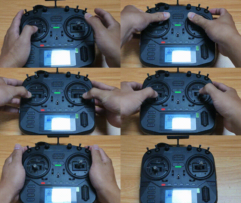
- Click Calibrate RC -> Click OK if prompted -> Move both the RC switch and stick to the maximum and minimum values -> Click Finish -> Click OK when the popup appears -> Calibration complete.
IV. Q&A
Technical Support QR Code