How to Set Up Custom LED Strips
I. Principles
Custom LED strips can achieve dynamic lighting effects based on settings from the flight controller or wireless board. Installing LED strips on the aircraft not only enhances aesthetics but also provides visual indication in different states. Through the wireless board or INAV ground control station (GCS), you can adjust the strip's color, on/off states, and even change its behavior based on flight data.
II. Equipment Preparation
1) Flight Controller: CoreWing F405 WING V2/SpeedyBee F405 WING APP / SpeedyBee F405 WING MINI - Any of these flight controllers are compatible with this tutorial.
2) LED Strip: WS2812 LED strip
3) INAV ground control station (GCS)
III. Specific Operations
3.1 CoreWing F405 WING V2 LED Pad Wiring

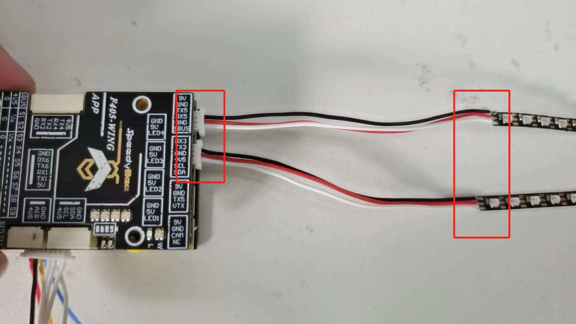
3.2 SpeedyBee F405 WING LED Strip Wiring
Important
SpeedyBee F405 WING APP: Connect the LED strip to one of the four interfaces below. If using two strips, connect to two interfaces. Note that the interface model is SH1.0 3P
※ Pay attention to the polarity and signal wire order


3.3 Wireless Board Control of LED Strip Effects
Applicable to SpeedyBee F405 WING APP
3.4 Flight Controller Control of LED Strip Effects
Important
Applicable to CoreWing F405 WING V2\SpeedyBee F405 WING MINI
Important
SpeedyBee F405 WING APP: Briefly press the BOOT button for 3 seconds, then release. Confirm that the orange indicator light on the top of the flight controller turns off, entering FC_LED mode.

Important
CoreWing F405 WING V2\SpeedyBee F405 WING MINI: Only FC_LED mode is supported; SB_LED mode is not supported.
3.4.1 Enable LED Output Switch
Open INAV ground control station, go to the Configuration page → check the LED output switch → click Save and Reboot.
3.4.2 LED Strip Settings
- Go to the LED Strip page → click Wire Ordering Mode → a green border will appear on the left side.

- Select any small square in the left panel, which will display a number.

The numbers displayed in the ground station represent the LED sequence starting from the flight controller connector end. If using two strips, they should match the first strip, with the LED closest to the connector being number 1.
- Change None to Color and save to enable setting LED colors, then click Save to apply to the strip.


Important
1. After each setting, you must click the save button marked with the red box in the bottom right corner for the LED strip to change.
2. A maximum of 32 LEDs can be configured.
3.4.3 Advanced Settings
1. RC transmitter control of LED strip on/off
Set the LEDS OFF channel in the Modes page to control the LED strip's on/off state with the RC transmitter
Important
Note: When LEDS OFF is on, the LED strip is off; when LEDS OFF is off, the LED strip is on;
2. Other LED functions
In addition to setting a constant LED state, there are many configurations based on different data that you can try by selecting the options marked below.
IV. Q&A
Technical Support QR Code