Receiver Screen Description - mLRS Firmware
I. Screen Overview
The mLRS firmware transmitter is equipped with an OLED screen that allows direct viewing of link status and parameter modification. The screen is divided into the following major pages:
| Page | Description |
|---|---|
| Main | Real-time telemetry data, with 5 sub-pages |
| Common | Common settings such as binding phrases, modes, RF settings |
| Tx | Transmitter parameter settings |
| Rx | Receiver parameter settings |
| Actions | Operation menu for storage, binding, firmware flashing, etc. |
II. Main Page
The main page displays real-time telemetry data and allows switching between 5 sub-pages using the rotary encoder.
2.1 Main - Signal Quality
Displays the current link's RSSI signal strength and LQ link quality, with the transmitter (Tx) on the left and receiver (Rx) on the right.
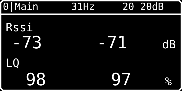
| Parameter | Description |
|---|---|
| Frequency | Current actual communication frequency |
| Power | Transmission power for Tx and Rx (unit dB) |
| Rssi | Received Signal Strength Indicator, unit dB, closer to 0 means stronger signal |
| LQ | Link Quality, unit %, 100% is best |
2.2 Main/2 - Sensitivity and Diversity
Displays mode, sensitivity, power, and antenna diversity information.
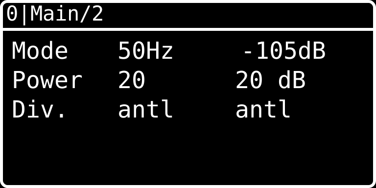
| Parameter | Description |
|---|---|
| Mode | Communication mode and rate (e.g., 50Hz) |
| Sensitivity | Receiver sensitivity (e.g., -105dB) |
| Power | Tx/Rx transmission power (unit dB) |
| Div. | Antenna diversity mode (antl = Antenna 1) |
2.3 Main/3 - Channels and Data Rate
Displays channel mapping and uplink/downlink data rates.
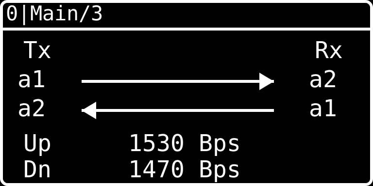
| Parameter | Description |
|---|---|
| Tx → Rx | Transmitter to receiver channel mapping (e.g., a1 → a2) |
| Rx → Tx | Receiver to transmitter channel mapping |
| Up | Uplink data rate (unit Bps) |
| Dn | Downlink data rate (unit Bps) |
2.4 Main/4 - Device Information
Displays device names and firmware versions for the transmitter and receiver.
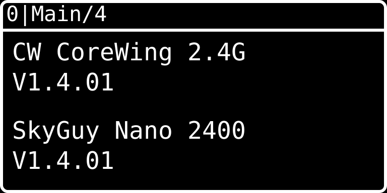
| Parameter | Description |
|---|---|
| Device Name | Transmitter model (e.g., CW CoreWing 2.4G) |
| Firmware Version | Transmitter firmware version (e.g., V1.4.01) |
| Receiver Name | Receiver model (e.g., SkyGuy Nano 2400) |
| Receiver Firmware | Receiver firmware version |
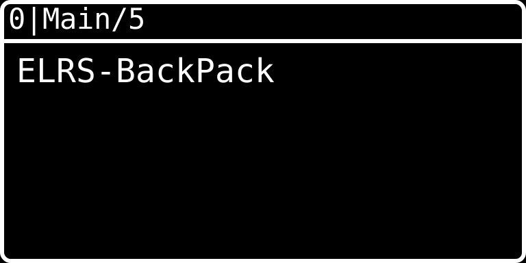
2.5 Main/5 - WiFi Bridge
Displays ELRS-BackPack WiFi bridge status.
III. Common Settings
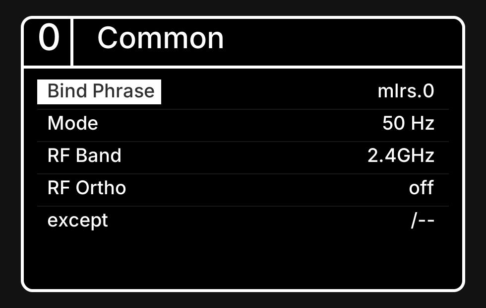
The common settings page includes basic parameters such as binding phrases, communication modes, and RF settings.
| Parameter | Description |
|---|---|
| Bind Phrase | Binding phrase, must match between transmitter and receiver for communication |
| Mode | Communication mode (e.g., 50 Hz) |
| RF Band | RF band (e.g., 2.4GHz) |
| RF Ortho | RF orthogonal mode, off means disabled |
| except | Exception handling settings |
IV. Transmitter Settings
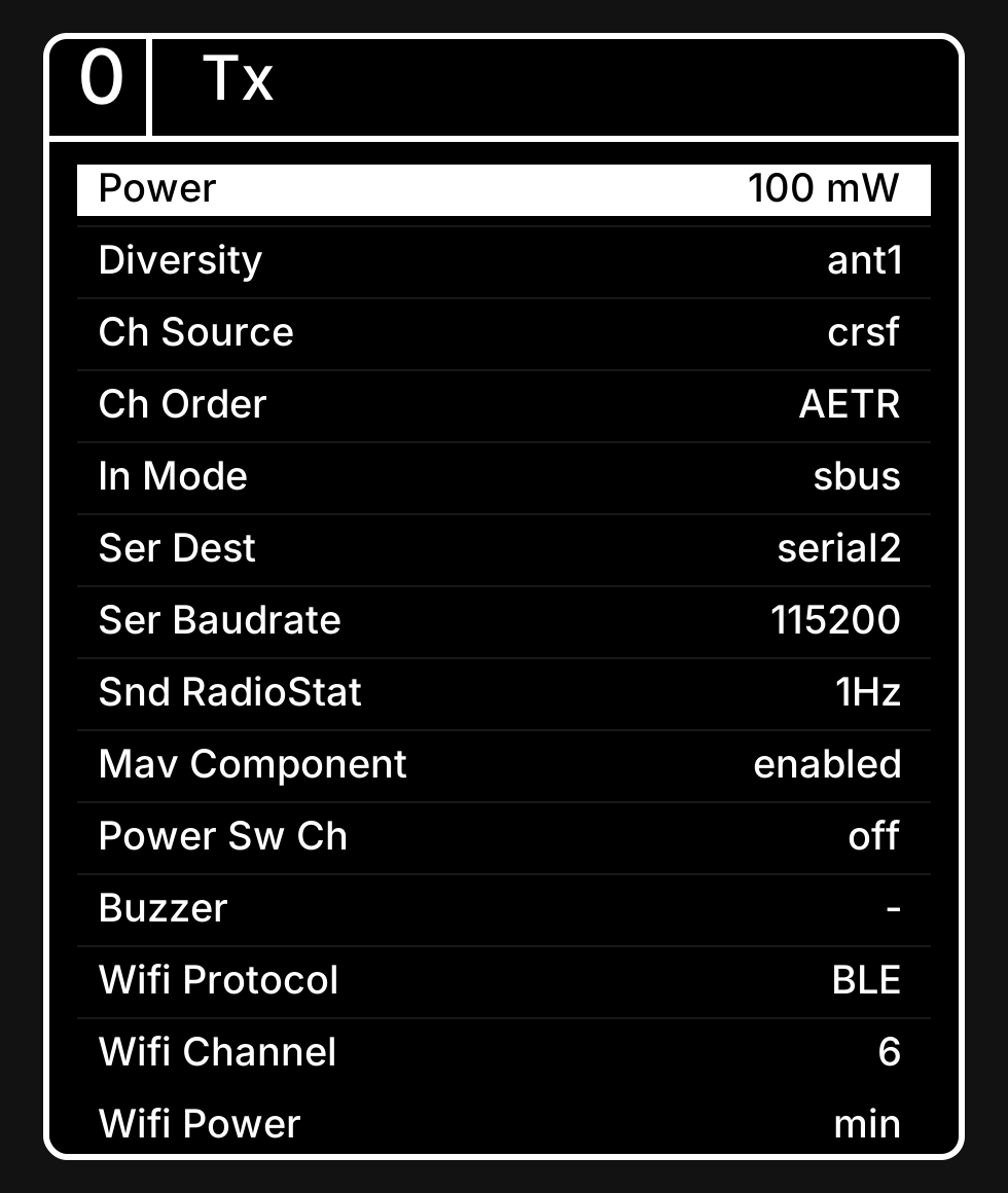
The transmitter settings page is used to configure various transmitter parameters.
| Parameter | Description |
|---|---|
| Power | Transmission power (e.g., 100 mW) |
| Diversity | Antenna diversity mode (ant1 = Antenna 1) |
| Ch Source | Channel source protocol (crsf = CRSF protocol) |
| Ch Order | Channel order (AETR = Throttle/Elevator/Rudder/Aileron) |
| In Mode | Input mode (sbus = SBUS protocol) |
| Ser Dest | Serial destination (serial2 = Serial 2) |
| Ser Baudrate | Serial baud rate (e.g., 115200) |
| Snd RadioStat | Frequency for sending radio status (e.g., 1Hz) |
| Mav Component | MAVLink component enable (enabled = enabled) |
| Power Sw Ch | Power switch channel (off = disabled) |
| Buzzer | Buzzer settings |
| Wifi Protocol | WiFi protocol (BLE = Bluetooth Low Energy) |
| Wifi Channel | WiFi channel (e.g., 6) |
| Wifi Power | WiFi power (min = minimum) |
V. Receiver Settings
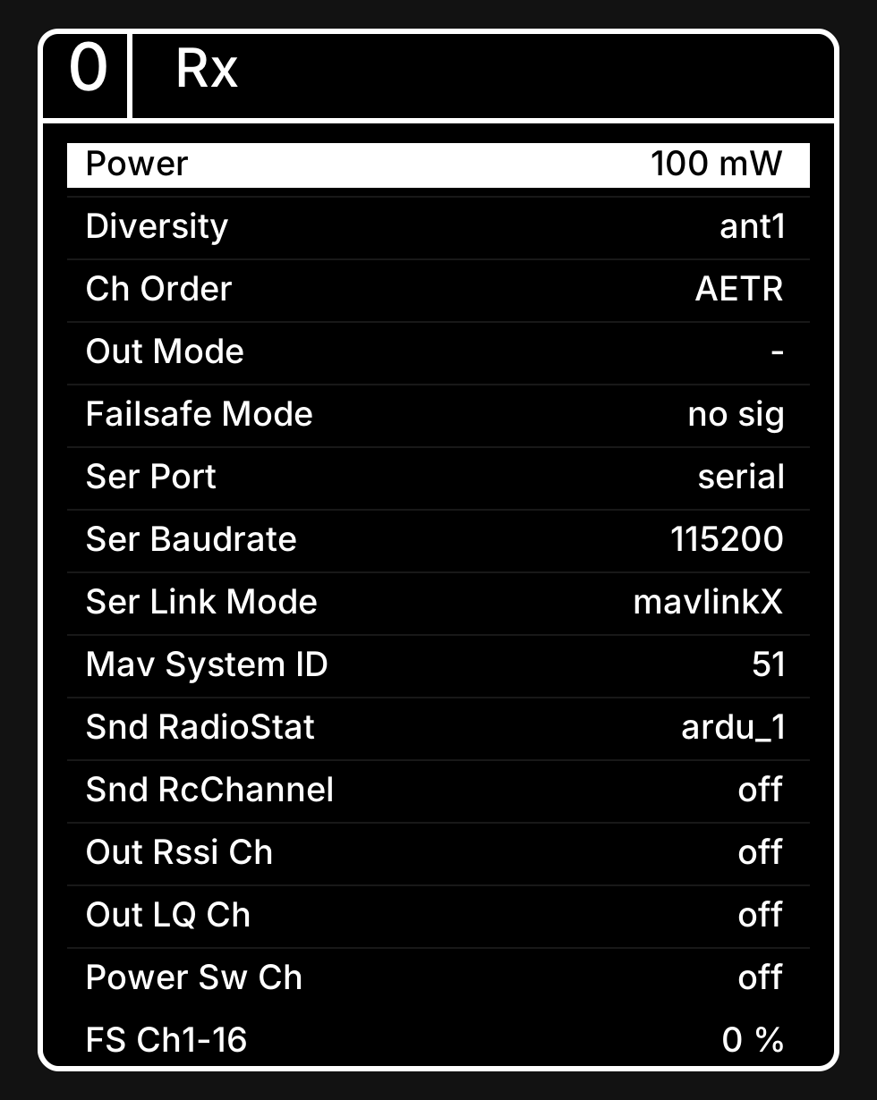
The receiver settings page is used to configure various receiver parameters.
| Parameter | Description |
|---|---|
| Power | Transmission power (e.g., 100 mW) |
| Diversity | Antenna diversity mode (ant1 = Antenna 1) |
| Ch Order | Channel order (AETR = Throttle/Elevator/Rudder/Aileron) |
| Out Mode | Output mode |
| Failsafe Mode | Failsafe mode (no sig = triggered when no signal) |
| Ser Port | Serial port (serial = Serial) |
| Ser Baudrate | Serial baud rate (e.g., 115200) |
| Ser Link Mode | Serial link mode (mavlinkX = MAVLink extended protocol) |
| Mav System ID | MAVLink system ID (e.g., 51) |
| Snd RadioStat | Frequency for sending radio status (ardu_1 = ArduPilot format) |
| Snd RcChannel | Send RC channel (off = disabled) |
| Out Rssi Ch | RSSI output channel (off = disabled) |
| Out LQ Ch | LQ output channel (off = disabled) |
| Power Sw Ch | Power switch channel (off = disabled) |
| FS Ch1-16 | Failsafe values for each channel (0%) |
VI. Actions Menu
The actions menu provides common operations such as saving settings, binding, and flashing firmware.
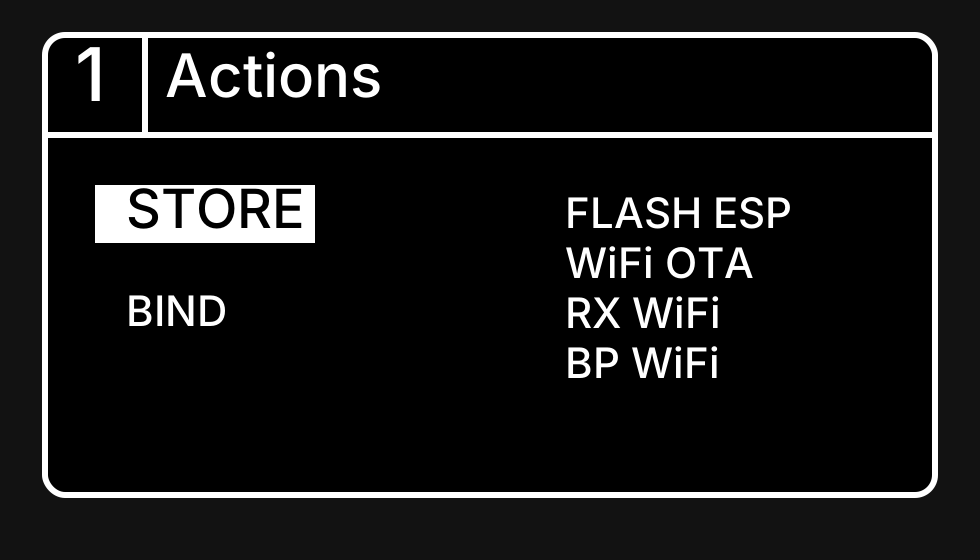
| Action | Description |
|---|---|
| STORE | Save all current settings to flash memory (selected state is white background with black text) |
| BIND | Enter binding mode |
| FLASH ESP | Flash ESP firmware |
| WiFi OTA | Start transmitter WiFi for upgrade |
| RX WiFi | Start receiver WiFi for upgrade |
| BP WiFi | Start BackPack WiFi connection |
Usage Tip
After modifying parameters, you need to go to the Actions page and select STORE to save successfully, otherwise the settings will be lost after reboot.
Technical Support QR Code
If you have any questions, scan the QR code to contact technical support: