How to use Mavlink for telemetry with Matek MLRS 2.4G MR24-30
I. How MLRS Works with Mavlink for Telemetry
MLRS Module Compared to Traditional RC + Telemetry Solution
The Matek MLRS 2.4G module integrates RC transmitter and telemetry functions into a single device, achieving a unified telemetry and control system with the following advantages:
Streamlined equipment: Only one module needs to be configured to handle both RC signal uplink and bidirectional telemetry communication, reducing the number of devices and connection complexity.
Stronger anti-interference capability: RC signals and telemetry data share the same radio link, reducing interference.
MLRS Mavlink Communication Working Principle
- RC Transmitter Signal Uplink
- The RC transmitter sends control signals (such as stick and switch operations) to the flight controller via radio signals through the MLRS high-frequency module.
- Bidirectional Telemetry Communication
The flight controller sends flight data (such as GPS position, battery level, flight controller status) back to the high-frequency module via radio signals through the MLRS receiver. Mobile devices can view this flight data by connecting to the high-frequency module via Bluetooth.
Mobile devices can connect to the MLRS high-frequency module via Bluetooth to send radio signals for configuring flight controller parameters, enabling wireless tuning.

II. Equipment Preparation
The following equipment is needed to implement this function:
1. Flight Controller (FC): CoreWing F405 WING V2 / CoreWing F405 WING MINI V2;
2. High-frequency Module: MATEK MLRS 2.4G High-frequency Module MR24-30-TX; (It is recommended to purchase a 3D printed case or print one yourself)
3. Receiver: MATEK MLRS 2.4G Receiver MR24-30-RX;
4. RC Transmitter: Radiomaster Boxer Transmitter - for reference only (Other RC transmitters with a JR bay can directly use the high-frequency module, while those without a JR bay require a purchase adapter).

High-frequency module case 3D printing files:
3. RC Transmitter Firmware Upgrade and Lua Script Import
1. RC Transmitter System Upgrade
✳When using the MLRS high-frequency module, the RC transmitter EdgeTX system must be upgraded to version 2.9.x or higher.
- Check if the RC transmitter's system version is greater than the minimum version required for this function.
Enter the RC transmitter SYS system menu → VERSION interface → View "VERS".
Color screen:

Black and white screen:

- For RC transmitter system upgrade, refer to the following article: https://docs.corewing.com/plane/other/edgetx/buddy-fw-update.html
2. Lua Script Import
- mLRS Lua script download:
※If using an RC transmitter with a 480*272 color screen (e.g., Jumper T16, Radiomaster TX16S), please download the "mLRS.lua" file.
※If using an RC transmitter with a black and white screen (e.g., Radiomaster Boxer), please download the "mLRS-bw.lua" file.
3. MLRS High-Frequency Module and Receiver Settings
1) Receiver Connection to Flight Controller:
Solder the receiver's DuPont connectors and insert them into the flight controller's CRSF receiver interface, ensuring the receiver's TX connects to the flight controller's RX and the receiver's RX connects to the flight controller's TX.

2) Enable Bluetooth Mode for the High-Frequency Module:
Switch all DIP switches of the high-frequency module to "ON"/left position, at which point the mLRS high-frequency module will enable Bluetooth mode.

3) RC Transmitter Settings:
① Since mLRS officially only supports 400k baud rate, in the EdgeTX/OpenTX system, enter MDL→MODEL SETUP, turn off internal RF, turn on external RF, select CRSF protocol, and set baud rate to 400k.
② Color screen settings:


③ Black and white screen settings:

| Internal RF off | |
|---|---|
| Parameter | Set to |
| Internal RF | OFF |
| External RF on and set parameters | |
| --- | --- |
| Parameter | Set to |
| External RF | |
| Mode | CRSF |
| Baudrate | 400k |
4) Bind the High-Frequency Module with the Receiver:
How to Put the Receiver into Binding Mode:
Method one: Press the binding button on the receiver for 4 seconds, indicator light 1 and indicator light 2 will alternately flash yellow and green, indicating it has entered binding mode;

- Method two: Power cycle the receiver 3 times quickly, the receiver will enter binding mode on the 4th power-on, indicator light 1 and indicator light 2 will alternately flash yellow and green, indicating it has entered binding mode.
How to Put the High-Frequency Module into Binding Mode:
- Method one: Press the binding button on the back of the high-frequency module for 4 seconds, indicator light 3 and indicator light 4 will alternately flash yellow and green, indicating it has entered binding mode;

- Method two: Enter binding mode through the mLRS Lua script, indicator light 3 and indicator light 4 will alternately flash yellow and green, indicating it has entered binding mode.
Color screen:

Black and white screen:

| Indicator light status after successful binding | ||
|---|---|---|
| Receiver | Indicator light 1 | Slow yellow flash |
| Indicator light 2 | Off | |
| High-frequency module | Indicator light 3 | Slow yellow flash |
| Indicator light 4 | Off |
5) Parameter Settings
High-frequency module parameter settings:
① Enter the Lua script and modify the following parameter settings;
② Color screen: Click Edit Tx to enter high-frequency module parameter editing:


Or black and white screen: Click next to find the Tx related parameters.

| Parameter | Set to |
|---|---|
| Tx Power | 500mW |
| Tx Ch Source | crsf |
| Tx Ser Dest | serial |
| Tx Ser Baudrate | 115200 |
Receiver parameter settings:
① Enter the Lua script and modify the following parameter settings;
② Color screen: Click Edit Rx to enter receiver parameter editing:


Or black and white screen: Click next to find the RX related parameters.


| Parameter | Set to |
|---|---|
| Rx Power | 500mW |
| Rx Out Mode | crsf |
| Rx Ser Baudrate | 57600 |
| Rx Ser Link Mode | mavlinkX |
| Rx Snd RadioStat | ardu_1 |
| Rx Snd RcChannel | rc_override |
IV. Flight Controller Parameter Settings
- Query the flight controller serial port used by the receiver:
Confirm the receiver's RX is connected to the flight controller's TX, and the receiver's TX is connected to the flight controller's RX:

CoreWing F405 WING V2 / CoreWing F405 WING MINI V2 uses SERIAL 6:
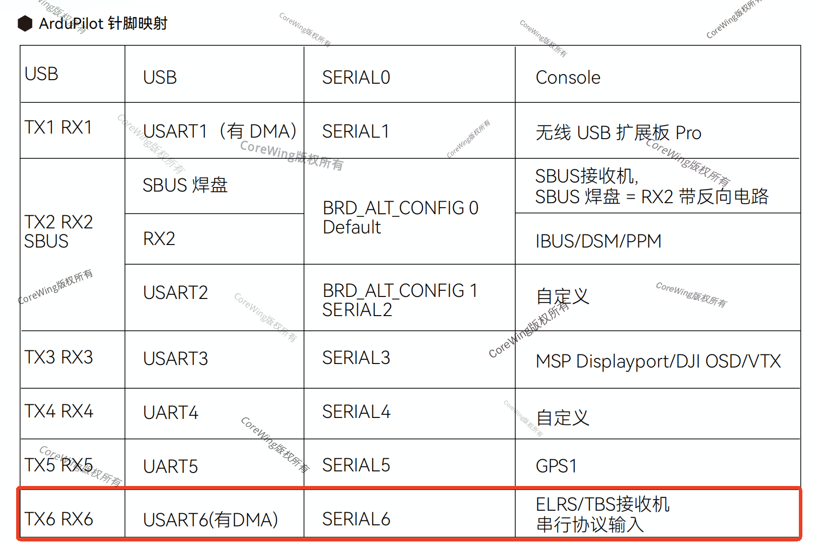
SpeedyBee F405 WING APP/SpeedyBee F405 WING MINI uses SERIAL 1:

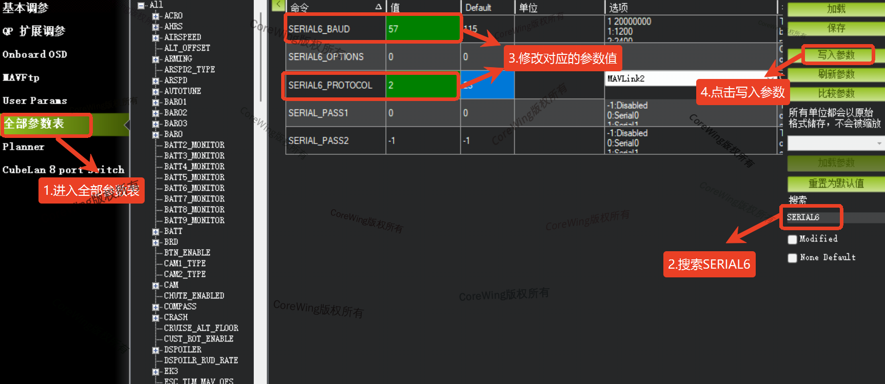
- Parameter Settings
Connect the flight controller using a USB data cable and open Mission Planner software to connect to the flight controller.
Enter the "All Parameters" page.
Set SERIALX_BAUD to 57600.
Set SERIALX_PROTOCOL to Mavlink2.
Click "Save Parameters" to confirm the settings.
After completing the settings, disconnect the flight controller power and restart the flight controller.
CoreWing F405 WING V2 / CoreWing F405 WING MINI V2 settings in ground control station:
SpeedyBee F405 WING APP/SpeedyBee F405 WING MINI settings in ground control station:


V. Remote Control Uplink Signal Communication Confirmation
Reconnect the flight controller to the computer using a USB data cable and complete the connection operation in MissionPlanner ground control station.
Enter the initial settings, remote control calibration page, and check if the flight controller can receive data input from the remote control.

- If data is displayed in the remote control calibration interface, it means the uplink between the remote control and flight controller has successfully established communication. If there is no data in the calibration interface, return to Check the parameter settings of the transmitter and receiver
VI. Telemetry Link Bidirectional Communication Confirmation
- Enter the remote control's MDL menu → TELEMETRY interface → Expand Sensors to view the data currently received by the transmitter.

- If only the receiver's signal data is displayed, it means communication has not been established between the transmitter and flight controller, Check the flight controller parameter settings and the wiring between the receiver and flight controller.

- If data information from the flight controller is received, it means the telemetry link has successfully established communication and the telemetry function can be used normally.
VII. Ground Control Station Connection Settings
7.1 MissionPlanner Connection Tutorial
- Turn on the computer's Bluetooth, find Matek-mLRS-BT, and pair with it. The default Bluetooth PIN is: 1234;

- Open MissionPlanner, select Serial (COM X) on COM X Bluetooth link, select connection baud rate as 115200, and click connect;

※Note: There may be two Bluetooth COM ports, connect to either COM port. If the connection is not successful, switch to the other one.
- After the ground control station finishes acquiring parameters, the connection is successful. Open the link statistics to view the link data.

7.2 QGroundControl Connection Tutorial
After confirming that the remote control and telemetry functions of MLRS can be used normally in Mission Planner ground control station, connect to other ground control stations for operation.
The specific settings are as follows:
Open QGC ground control station, click the QGC icon in the upper left corner.
Select Application Settings.
Enter Communication Connection.
Click Add.
Set Name to MLRS, set Type to Serial Port, set Serial Port to COM X (the serial port used by Bluetooth), and set Baud Rate to 115200.
Click Confirm to save the settings.
Return to the Communication Connection interface, select MLRS
Then click Connect.


- When the status in the upper left corner of QGC changes from Disconnected to Not Ready or Ready to Fly, it means the connection is successful. Just wait for the parameter reading to complete.

| Comparison table of Mavlink telemetry communication effects using different devices | ||||
|---|---|---|---|---|
| Link quality at 500m (%) | Packet rate at 500m (packets/s) | Link quality at 1000m (%) | Packet rate at 1000m (packets/s) | |
| Telemetry | 95~100% | 56~58 | 95~100% | 56~58 |
| MLRS 2.4G transmitter-BLE | 90~100% | 55~60 | 90~100% | 55~60 |
| ELRS 2.4G transmitter-USB | 90~100% | 55~60 | 90~100% | 55~60 |
| ELRS 2.4G transmitter-WiFi | 90~100% | 55~60 | 90~100% | 55~60 |
VIII. Q&A
Q: If there is remote control output but no control surface response from the aircraft, and the remote control input interface in the ground control station shows no value changes?
A: Use MissionPlanner ground control station to check:
Confirm the receiver connection cable is not damaged, the transmitter interface pins and sockets are not deformed → Confirm the transmitter and receiver are on the same frequency → Confirm the parameter configuration of the transmitter and receiver is correct → After making modifications, power off and restart the transmitter, receiver, and flight controller → Connect again.
Q: If there is remote control output and the aircraft responds, but the transmitter's Bluetooth mode cannot connect to the ground control station?
A: Use MissionPlanner ground control station to check:
Confirm the baud rate of the serial port used by the receiver is set to 57600, and the protocol is Mavlink → After making modifications, power off and restart the transmitter, receiver, and flight controller → Confirm that the connection baud rate selected when connecting to the ground control station via Bluetooth is 115200.
Q: If the Bluetooth COM port cannot connect and all parameters are set correctly?
A: Cancel the Bluetooth pairing, close the ground control station, re-pair, then open the ground control station and connect again.
Technical Support QR Code