INAV 4+1 VTOL Parameter Tuning Guide
I. Flight Principle Introduction
Vertical take-off and landing (VTOL) fixed-wing drones combine multirotor and fixed-wing technologies, using multirotors for vertical take-off and landing, and switching to fixed-wing mode through a transition mechanism for efficient horizontal flight. During horizontal flight, lift is generated by the wings, and direction and attitude are adjusted by control surfaces.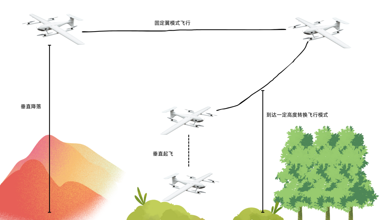
II. Equipment Preparation
Required Equipment:
1) Flight Controller: CoreWing F405 WING V2 flight controller.
2) RC Transmitter: Using RadioMaster Boxer /RadioMaster TX16S RC transmitter as an example.
3) Receiver: Using SpeedyBee ELRS Nano 2.4G RX receiver as an example.
4) GPS Module: Using Beizheng BZ-251 GPS module as an example .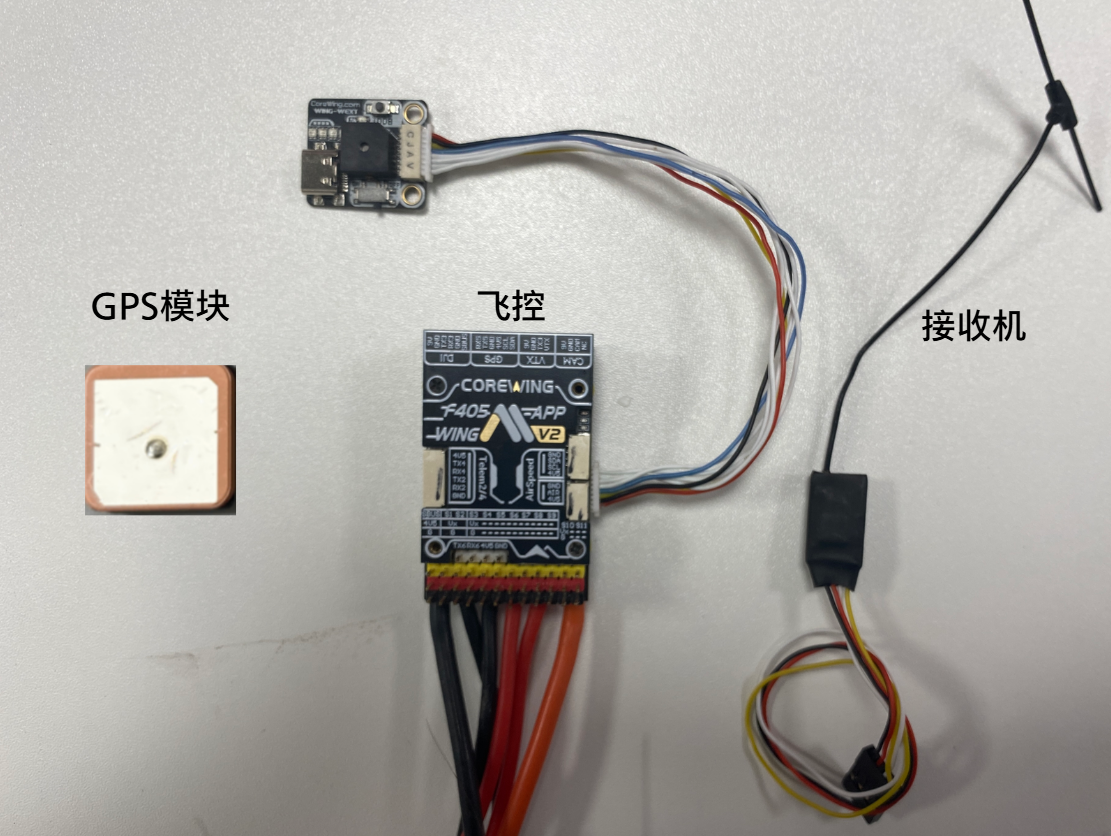
5) Motors: Using 2004 1600KV motors *4 (multirotor), 2807 1050KV motor *1 (fixed-wing), suitable for Adair 4+1 VTOL, for reference only.
6) ESCs: Using 45A ESCs, suitable for Adair 4+1 VTOL, for reference only.
7) Servos: Using 9g metal digital servos, suitable for Adair 4+1 VTOL, for reference only.
8) Battery: Using JP40 6S1P 4000mah 21700 battery, suitable for Adair 4+1 VTOL, for reference only.
9) Propellers: Multirotor motors use 5126 two-blade propellers, tail pusher motor uses 7040 three-blade propellers, suitable for Adair 4+1 VTOL, for reference only.
Optional Equipment:
1) Analog VTX: Using SpeedyBee TX 1600 VTX and RunCam Phoenix2 SE V2 camera as an example.
2) HD VTX: Using DJI O4 AIR UNIT VTX as an example.
3) Airspeed Sensor: Digital airspeed sensor is recommended.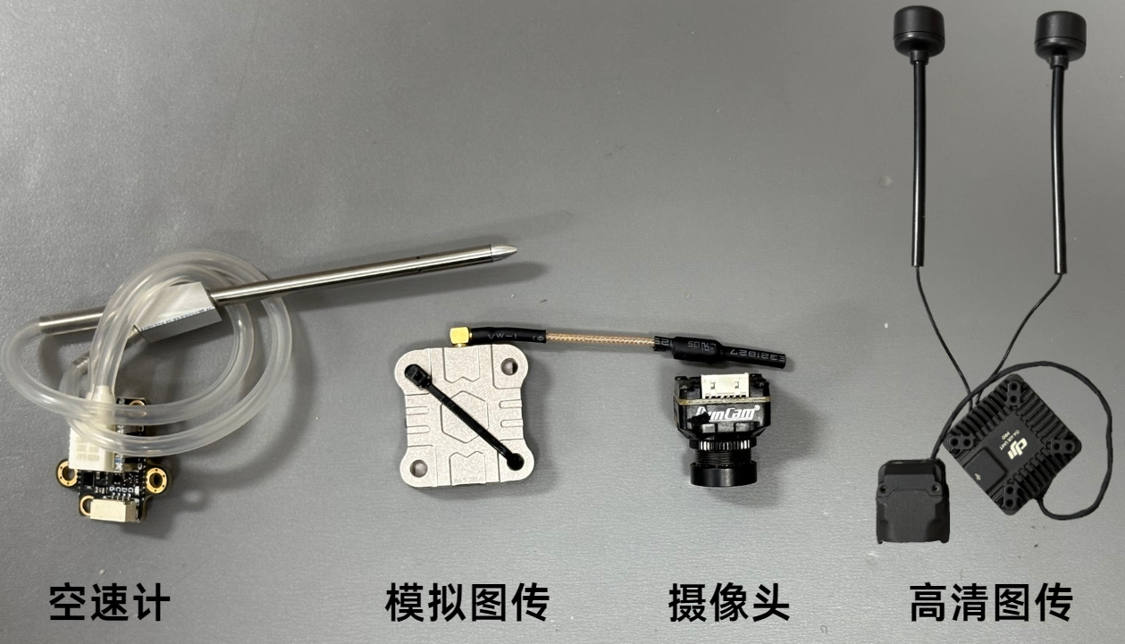
Important
Ground station installation can be referenced in this article: https://docs.corewing.com/plane/software/insoftware/inav-version-install.html
How to update flight controller firmware - using INAV ground station: https://docs.corewing.com/plane/beforetuning/inav-fw-update.html
III. Initial Setup
3.1 Accelerometer Calibration
Important
Note: When calibrating the accelerometer, be sure to remove the flight controller from the airframe and place it on a flat surface for calibration to improve accuracy and ensure stable flight!
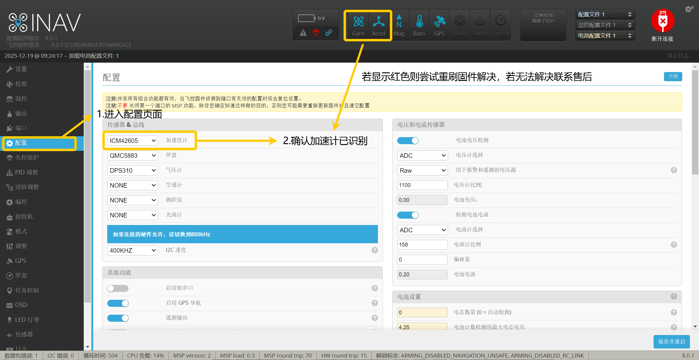
- Go to the Configuration page.
- Select Auto (auto-detect) and confirm that the accelerometer has been detected.
Important
If displayed in red, try closing and reopening the INAV ground control station connection. If the issue persists, contact technical support for flight controller firmware and reflash the firmware to resolve the issue!
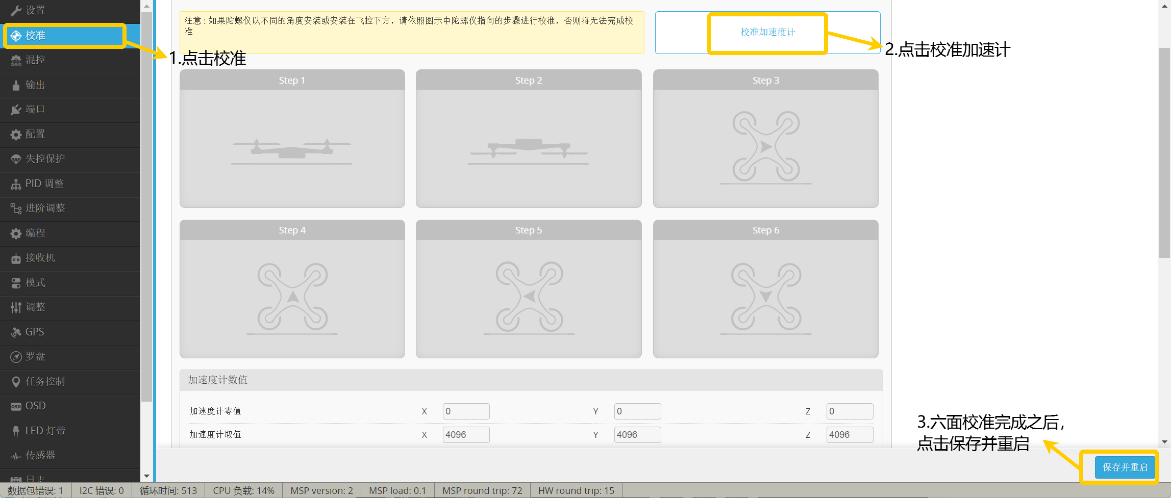
- Click Calibrate.
- Click Calibrate Accelerometer.
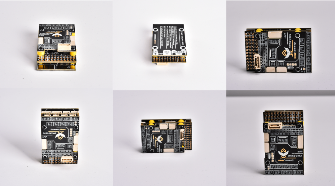
- Perform calibration according to the diagram.
Important
After calibrating each side, you need to click Calibrate Accelerometer once.
Important
The diagram below corresponds one-to-one with the accelerometer calibration above.
Important
After calibration is complete, click Save and Restart.
Important
The accelerometer needs to be recalibrated when there are significant temperature and climate changes during use, the gyro has suffered a severe impact, or sensors have been replaced!
3.2 Port Configuration
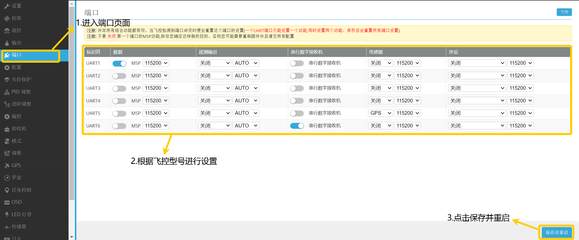
- Go to the Ports page
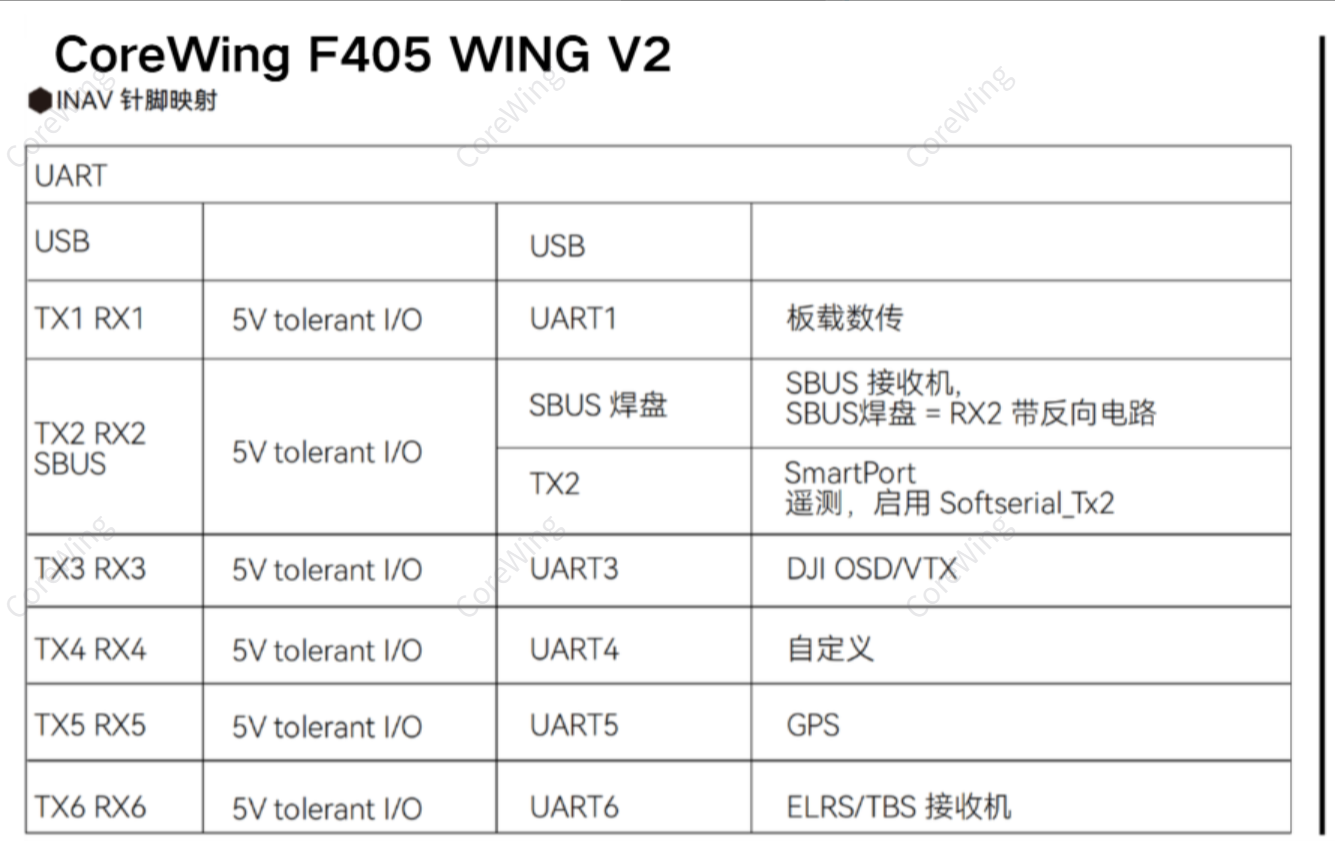
- Configure according to the table
- Click Save and Restart
3.3 Compass Calibration - For Enabling Related Flight Modes
Important
Note: Without compass calibration, you will not be able to switch between configuration files and mixer files.
Important
Connect the GPS module with built-in compass to the flight controller.
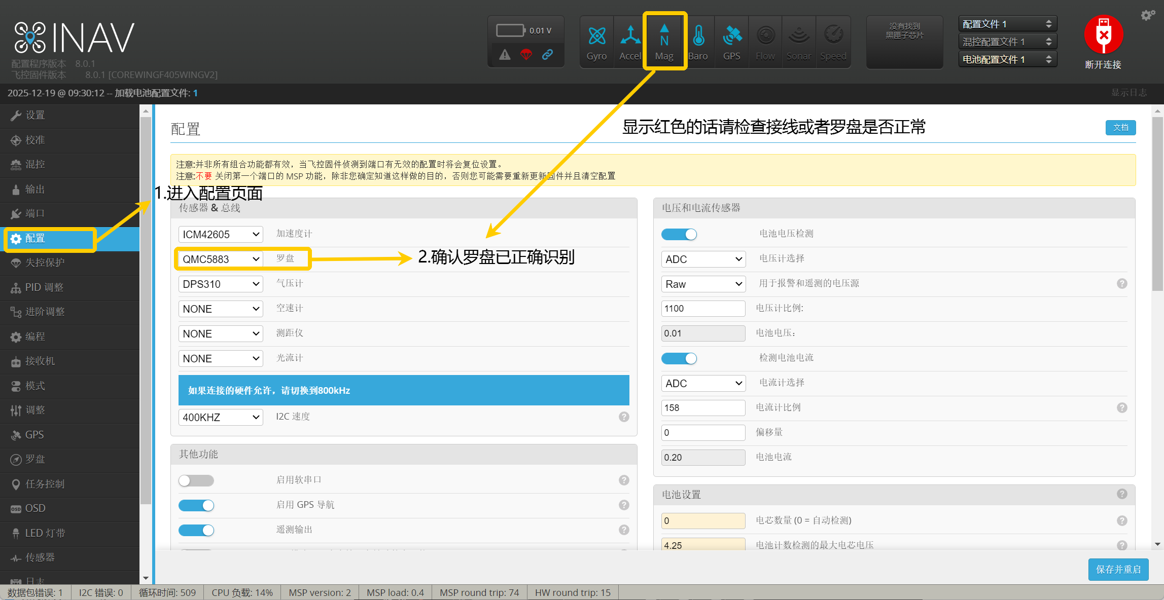
- Go to the Configuration page.
- Select Auto (auto-detect) and ensure the compass has been properly detected.
Important
If the compass icon is displayed in red, it means it has not been properly detected. Please check the wiring or if the compass is functioning properly!
- Go to the Calibration page.
- Click Calibrate Compass.
- No action is required, just wait for 30 seconds.
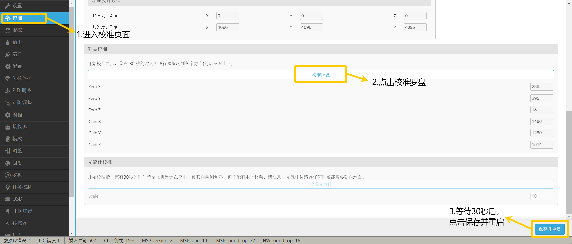
Important
After completion, click Save and Restart.
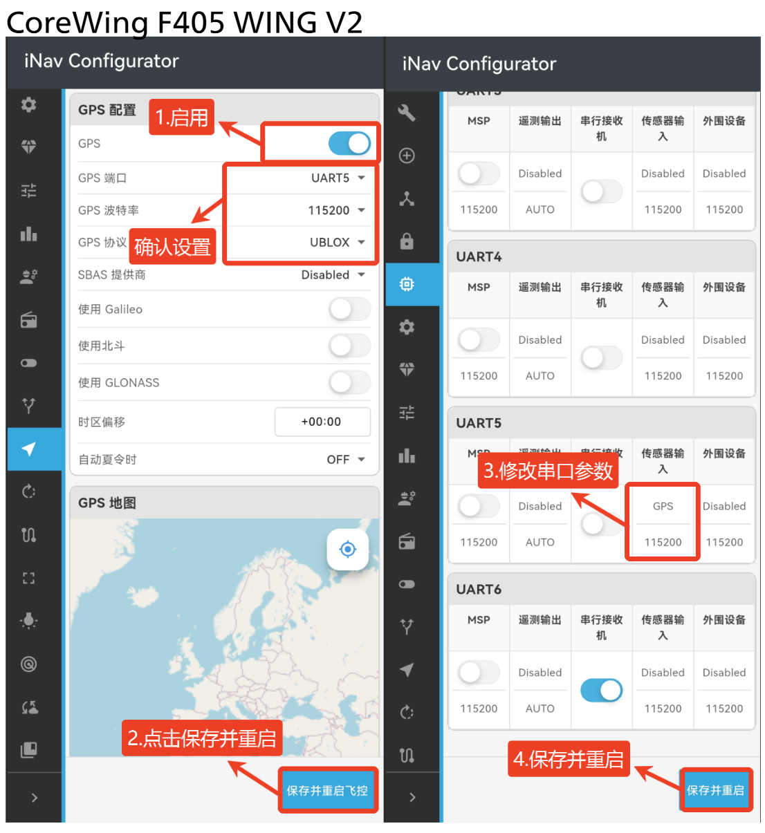
3.4 GPS Configuration
Important
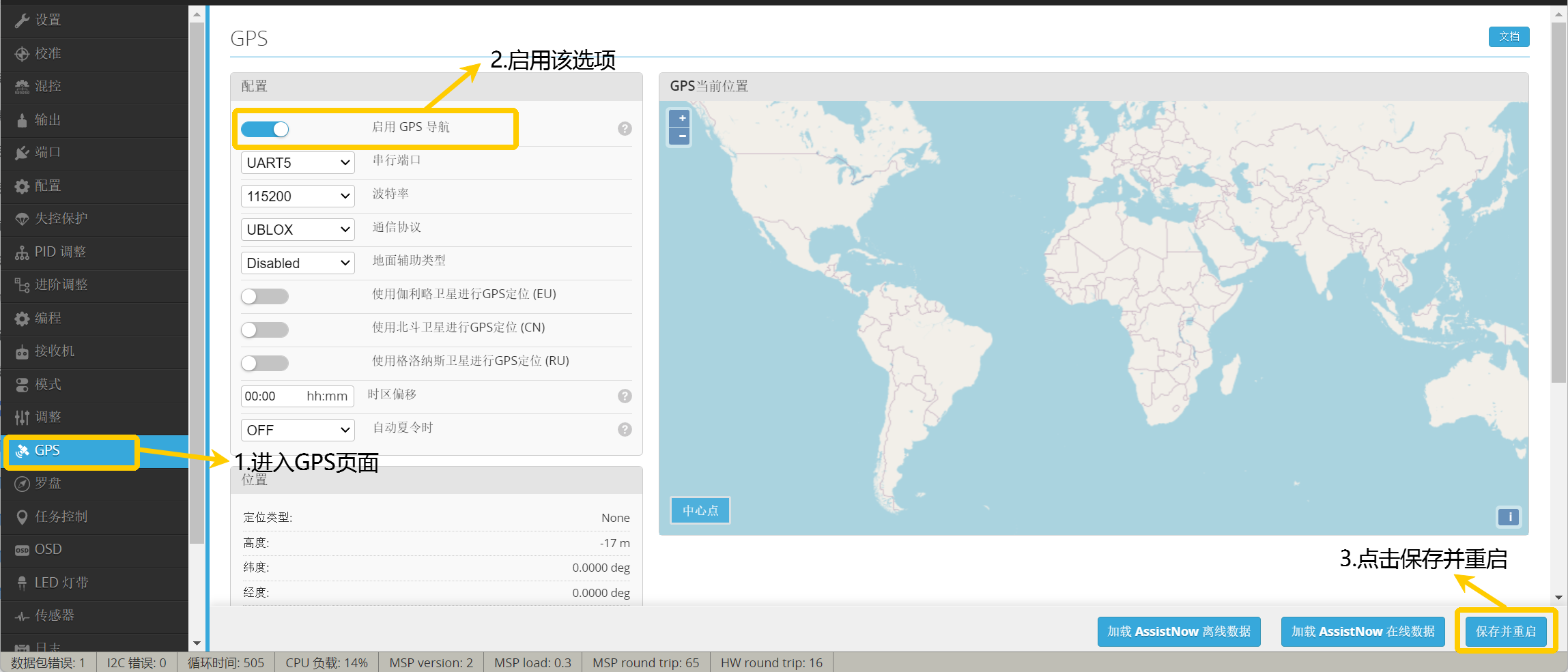
Enable GPS to view navigation-related flight mode settings in the Modes page.
- Go to the
GPSpage. - Enable the Enable GPS Navigation option.
- Click Save and Restart.
3.5 Transmitter and Flight Mode Settings
3.5.1 Transmitter Settings
Important
- Please bind the transmitter to the receiver before proceeding with the following steps.
- For information on how to bind an ELRS receiver to the transmitter, refer to this article: https://docs.corewing.com/plane/ardupilot/settings/rc/elrs-bind.html
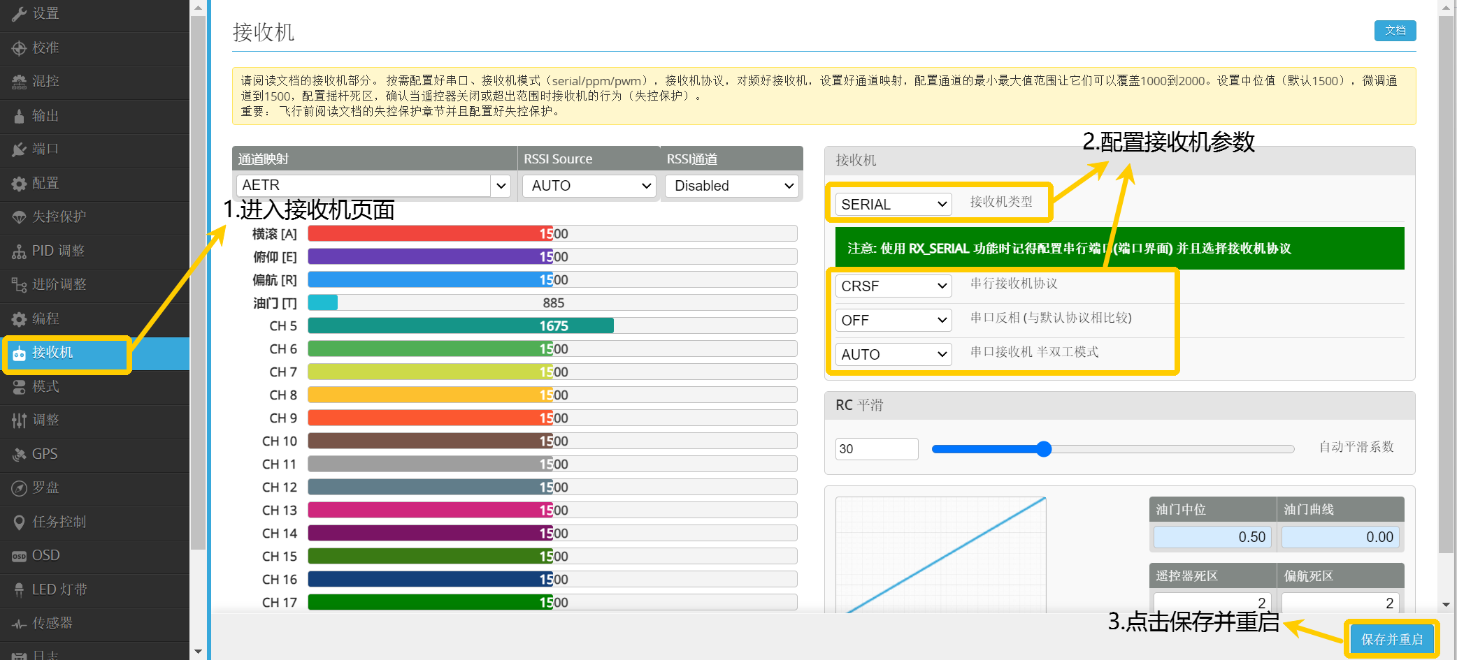
- Go to the Receiver page.
- Configure according to the receiver type.
- Click Save and Restart.
Important
For detailed information on how to set channel travel on EDGE TX, refer to this article: https://docs.corewing.com/plane/inav/settings/rc/edgetx-endpoint-setup.html
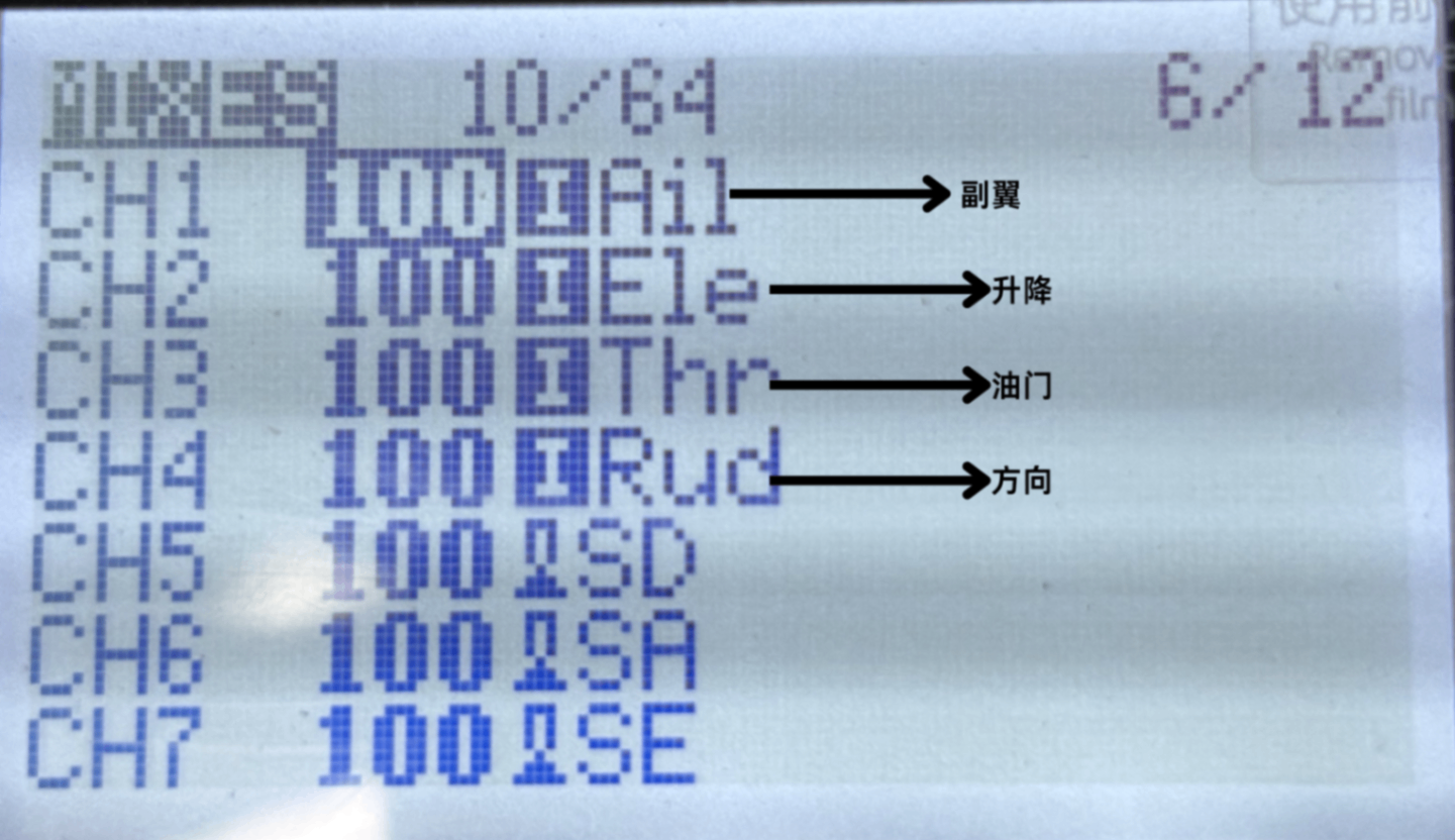
- Navigate to the MDL/MIXES page and check if the transmitter's CH1-CH4 are set as follows. If not, modify the transmitter mixer.
3.5.2 Arm Channel Settings
1. Transmitter Settings
- Select a 2-position switch
- Navigate to the MDL/MIXES page and configure its mixer as
CH5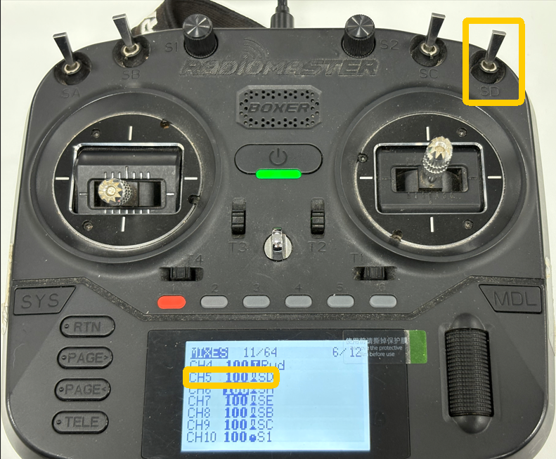
2. Ground Control Station Settings
Important
Note: The aircraft can only be armed in flight modes that do not require GPS, such as ANGLE (self-leveling). It cannot be armed in modes that require GPS, such as NAV ALT HOLD!
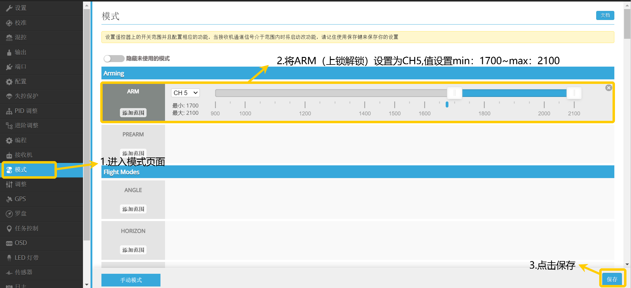
- Go to the Modes page.
- Set the
ARM(Arm/Disarm) channel toCH5, with values set between min:1700-max:2100. - Click Save.
3.5.3 Return-to-Home Channel Settings
1. Transmitter Settings
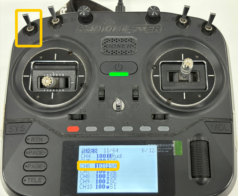
- Select a 2-position switch.
- Navigate to the MDL/MIXES page and configure its mixer as CH6 (can be set according to actual situation, for reference only).
2. Enable Return-to-Home Switch Settings
Important
By default, the return-to-home mode can only be activated when the aircraft is more than 5 meters away from the takeoff point. Within 5 meters, the OSD will not display the return-to-home mode!
- Go to the Modes page.
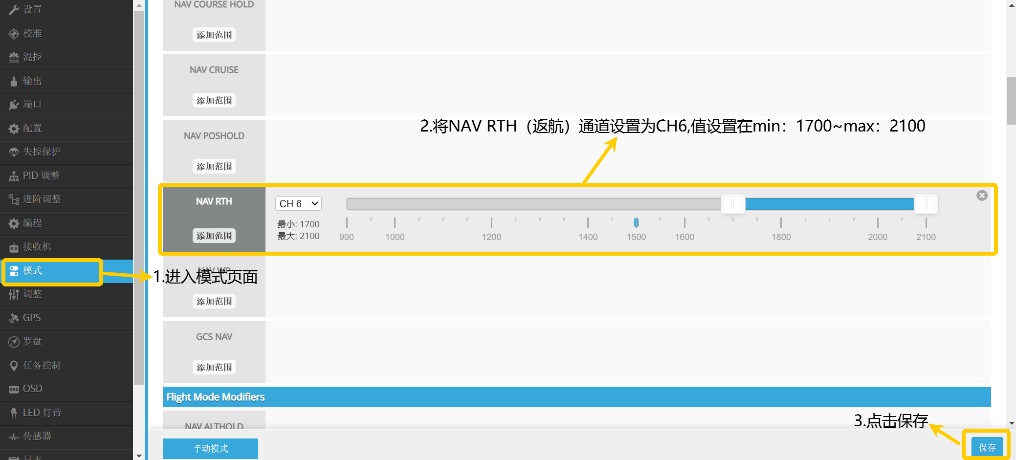
- Set the NAV RTH (Return-to-Home) channel to
CH6, with values set between min:1700-max:2100. - Click Save.
3.5.4 Flight Mode Settings
1. Transmitter Settings
- Select a 3-position switch to set the 3-position aircraft mode switch.
- Navigate to the MDL/MIXES page and configure its mixer as
CH8.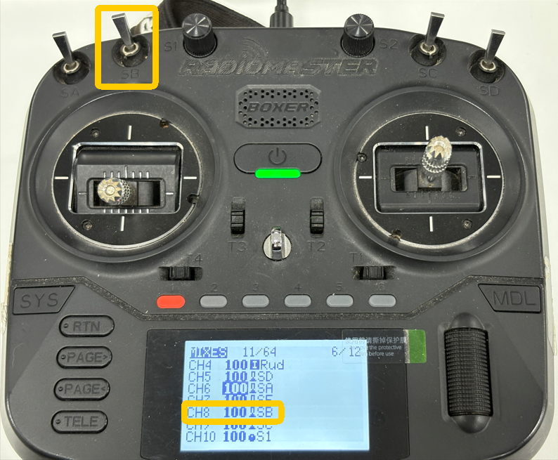
- Select another 3-position switch to set the 3-position flight mode switch.
- Navigate to the MDL/MIXES page and configure its mixer as
CH9.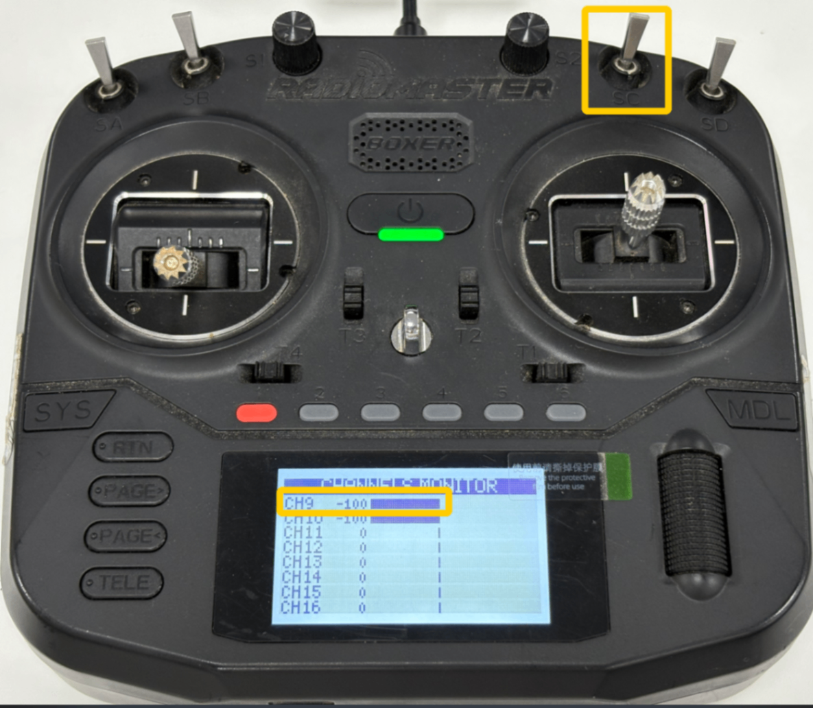
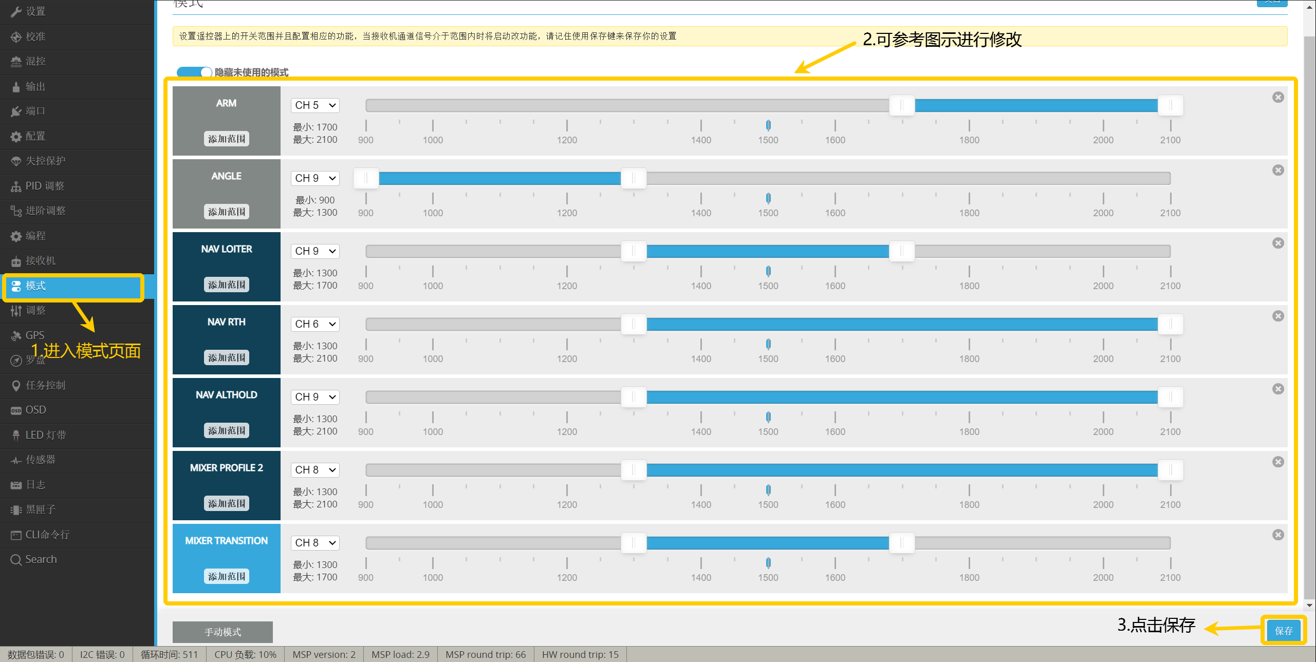
2. Ground Control Station Settings - Go to the Modes page.
- Make modifications according to the diagram.
- Click Save.
Important
Set the following to achieve the flight mode effect:CH8 is used to switch aircraft configuration, with the first position being Fixed-wing mode, the second position being Transition mode, and the third position being VTOL mode.CH9 is used to switch flight modes in VTOL configuration, with the first position being ANGLE (VTOL self-leveling), the second position being NAV LOITER (position hold) combined with NAV ALT HOLD (altitude hold), and the third position being NAV ALT HOLD (altitude hold).
Important
The altitude hold mode may have different names in different versions of the ground control station, such as NAV POSHOLD or NAV LOITER.
Important
For detailed information on flight modes, refer to this article: https://docs.corewing.com/plane/inav/settings/fc/flight-modes.html
IV. Equipment Installation
4.1 Flight Controller Wiring
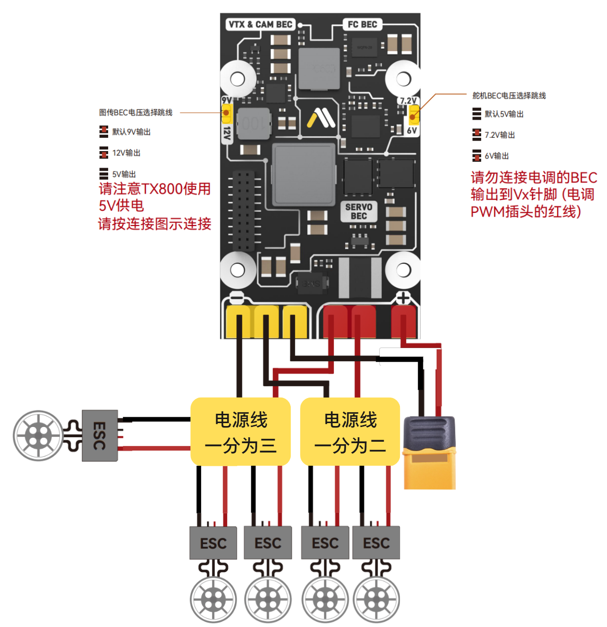
- Power Wiring
Important
Note:
- The positive power terminal must be connected to the designated pad.
- ESC refers to the electronic speed controller.
- When soldering, ensure there are no cold joints.
Important
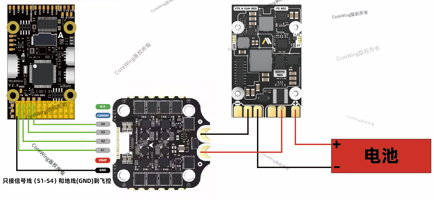
If using a 4-in-1 ESC for a racing drone (only connecting S1-S4 signal lines and GND ground wire), wire according to the diagram:
4.2 Flight Controller Installation
Important
The standard orientation for the flight controller should be aligned with the aircraft's nose direction, but on this aircraft, it is not convenient to install in this orientation, so the installation orientation needs to be changed.
If you need to adjust other installation orientations for the flight controller, you can refer to this article for settings: https://docs.corewing.com/plane/inav/settings/fc/fc-orientation.html
The flight controller should be installed at the center of gravity of the aircraft and the center position of the three motors. Refer to the following diagram for installation: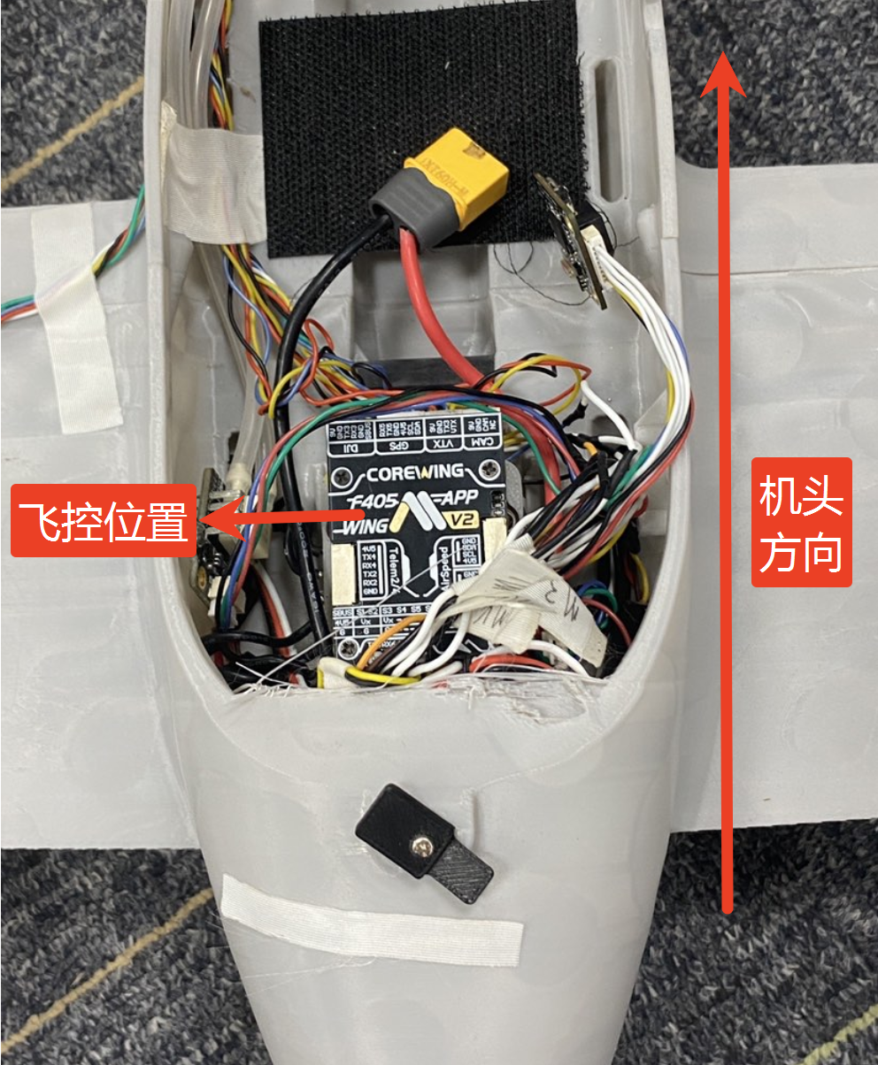
4.3 Peripheral Installation and Setup
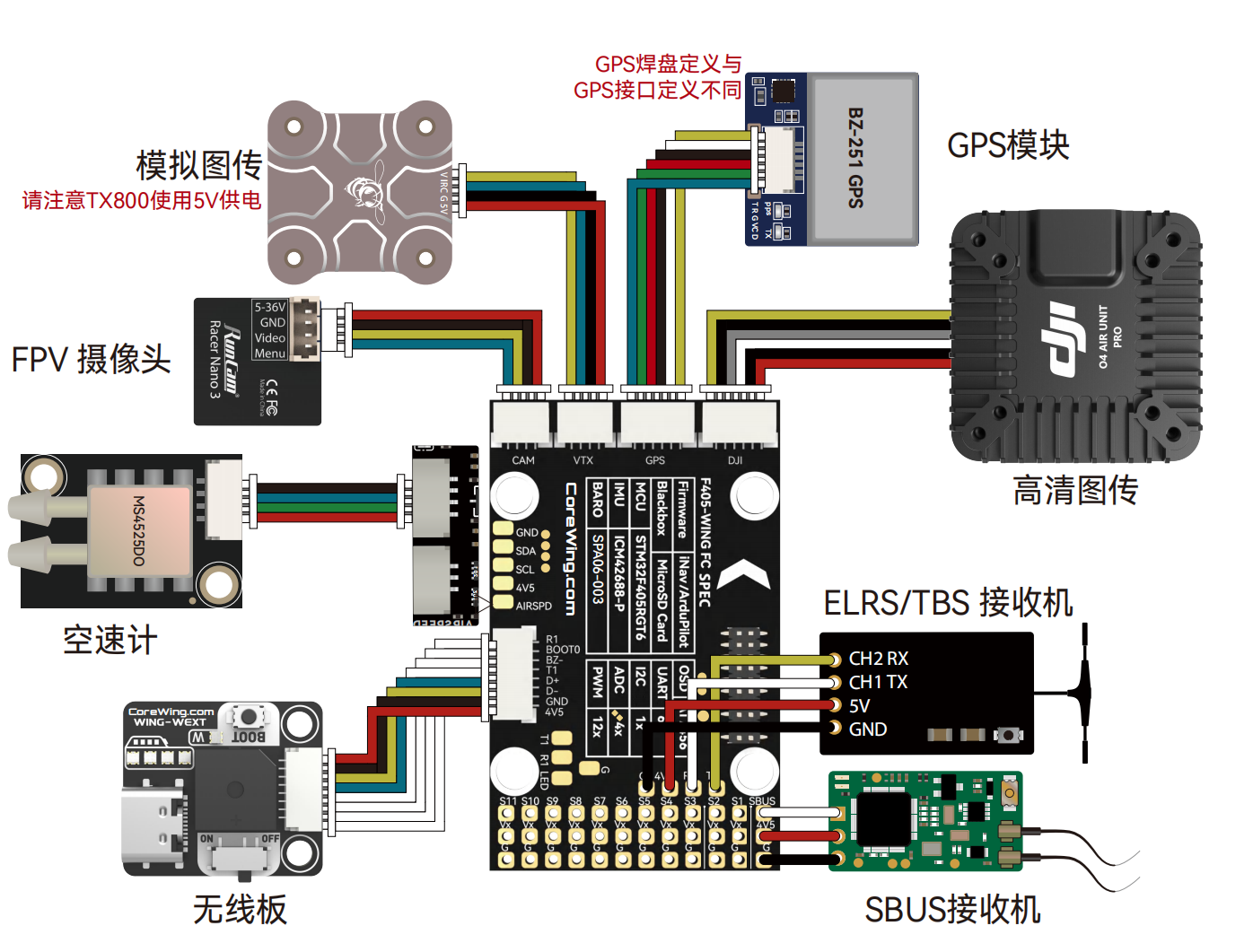
- Peripheral Wiring
4.3.1 Receiver Installation
The installation position is shown in the figure. Extend the antenna outside the aircraft and secure it with tape: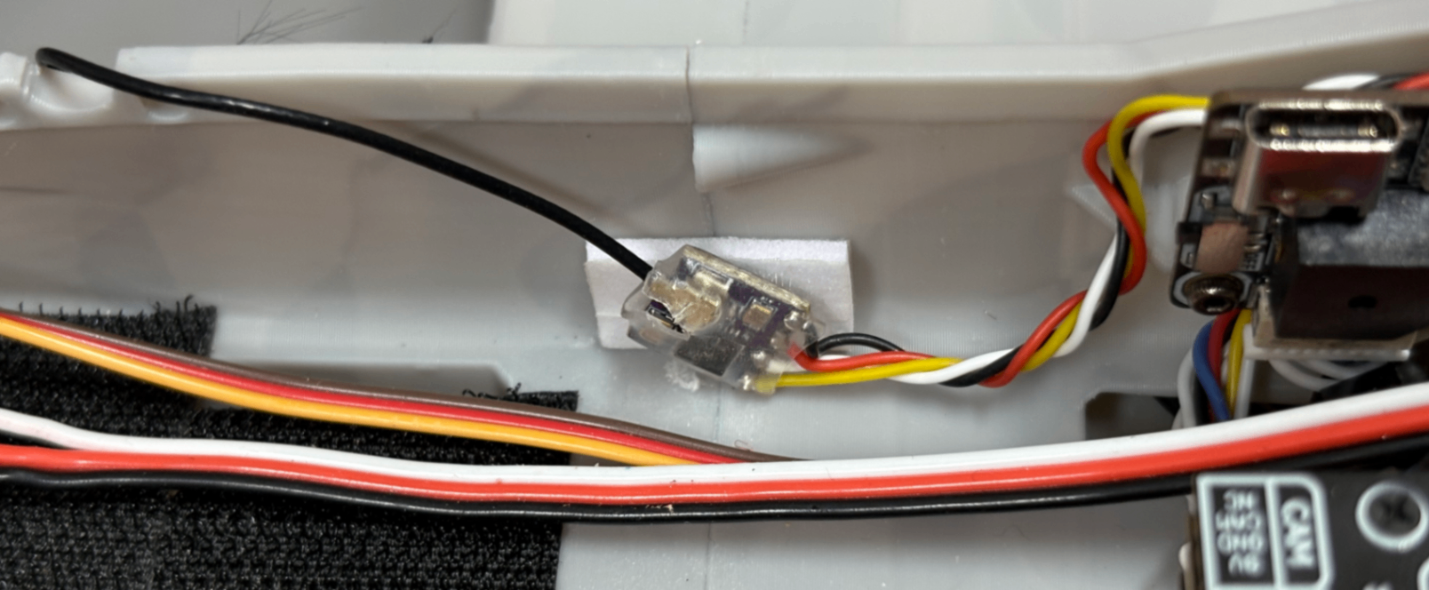
4.3.2 Mixer and Output Settings
Important
Disconnect the RC transmitter from the flight controller first, otherwise it will affect switching mixer configuration files in the ground control station!!
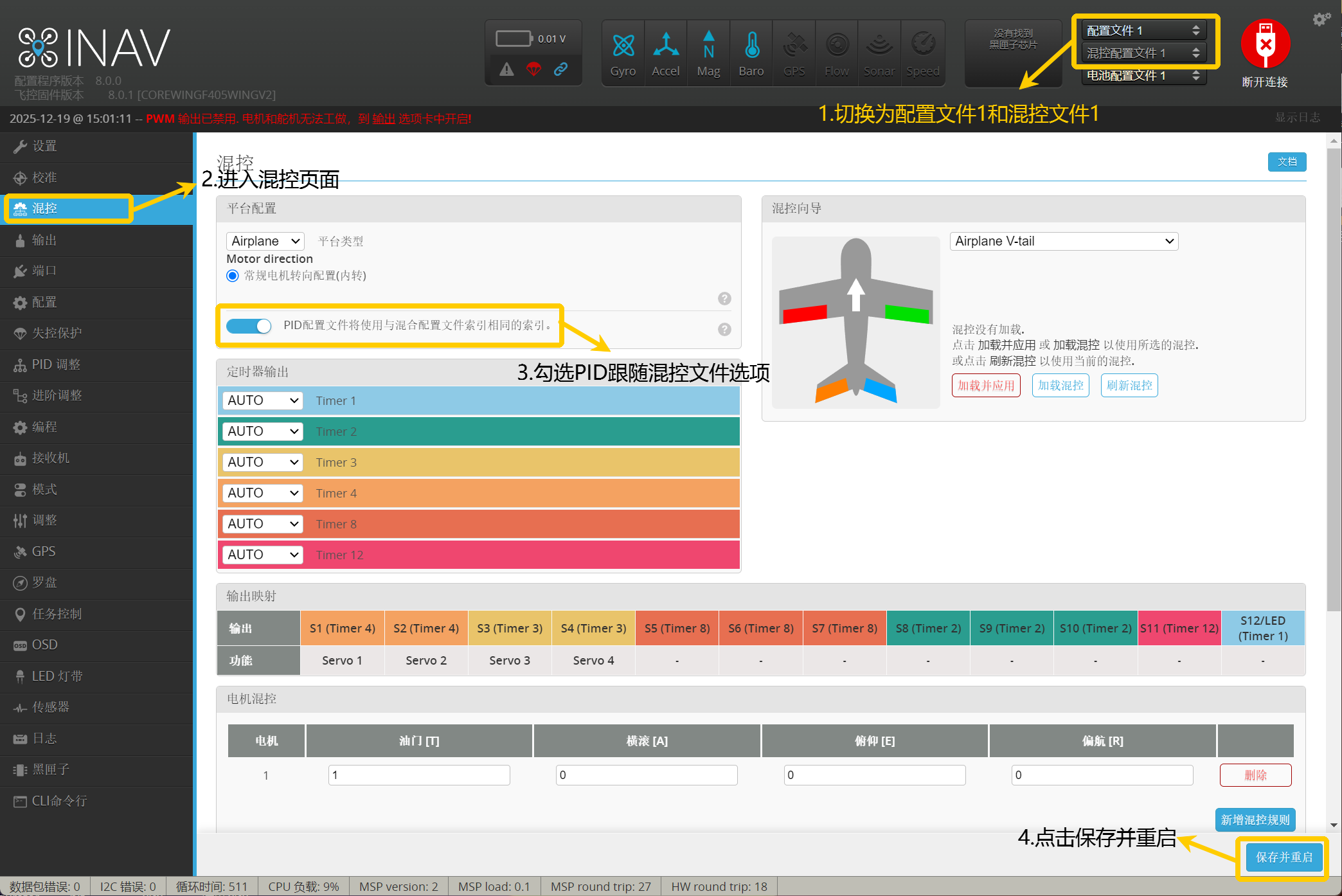
- Click the upper right corner to switch to Configuration File 1 and Mixer File 1, which is the fixed-wing mode.
- Enter the Mixer page and check "PID configuration file will use the same index as the mixer configuration file index", then click Save and Restart.
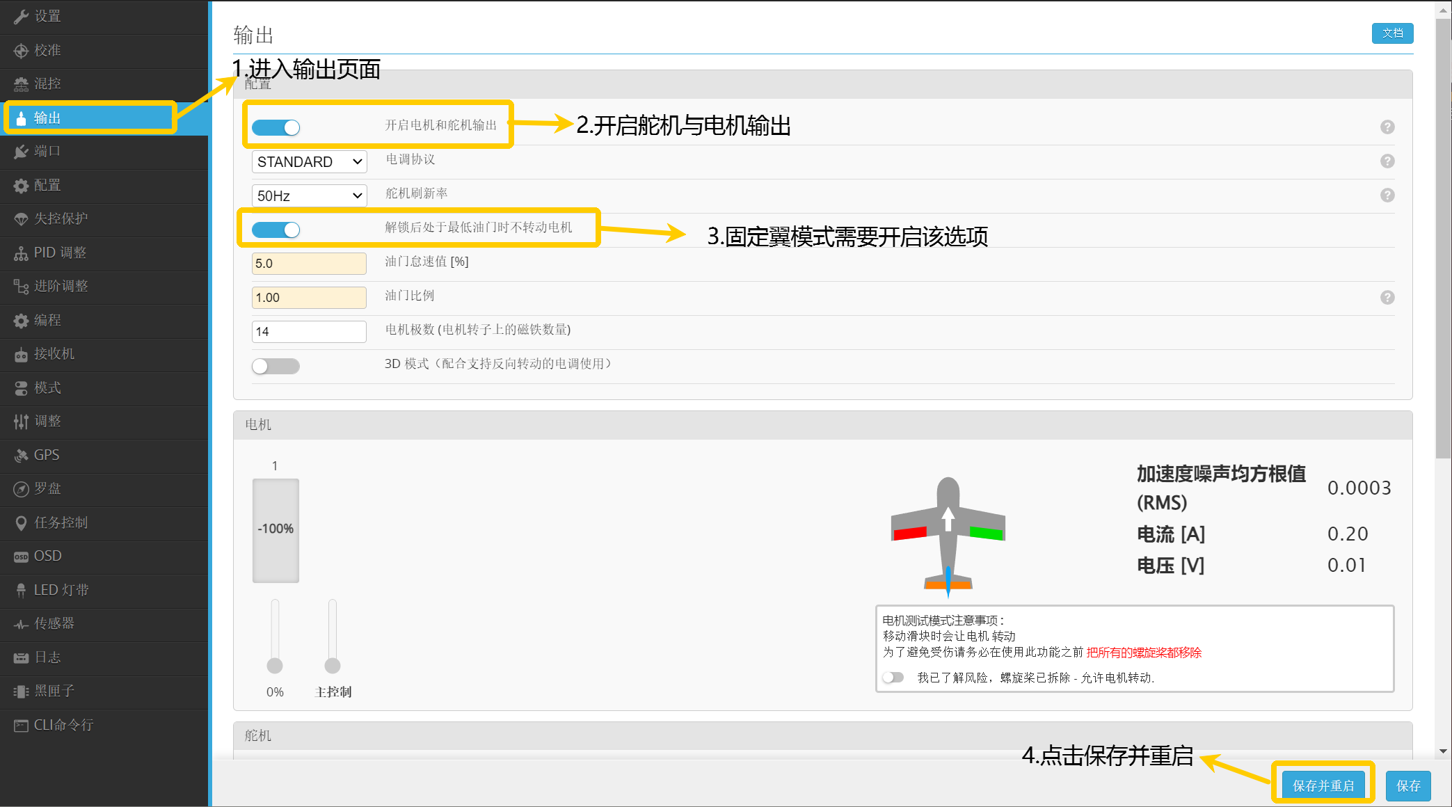
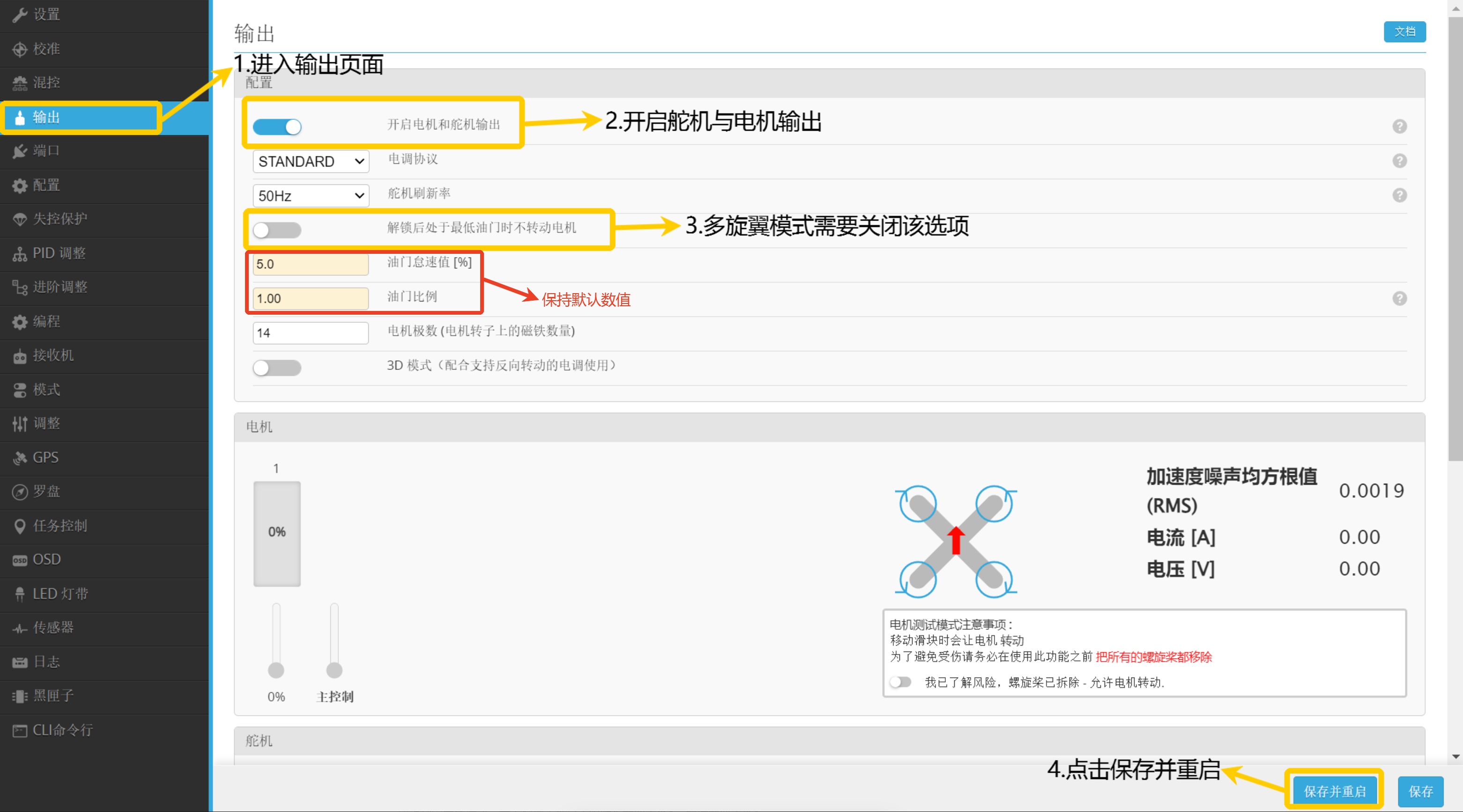
- Enter the Output page, enable motor and servo output and motors not rotating at minimum throttle after unlocking, click Save and Restart.
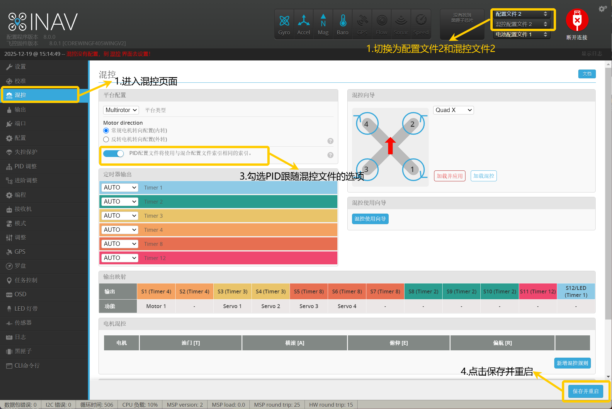
- Click the upper right corner to switch to Configuration File 2 and Mixer File 2, which is the VTOL mode.
- Enter the Mixer page and check "PID configuration file will use the same index as the mixer configuration file index", then click Save and Restart.
- Enter the Output page, enable motor and servo output and motors not rotating at minimum throttle after unlocking, click Save and Restart.
Important
- After enabling servo and motor outputs, the motors and servos can operate.
- In fixed-wing mode, it is necessary to enable motor prohibition at low throttle to prevent unnecessary damage from motors starting up after unlocking.
- In multirotor mode, remember to disable motor prohibition at low throttle to enable idle.
4.3.2.1 Checking Mixer File Switching
Important
CH8 is used for changing aircraft configuration, the first section is fixed-wing mode, the second section is transition mode, and the third section is VTOL mode.
- Pair the RC transmitter and receiver, and re-establish connection with the flight controller
- Toggle the RC transmitter CH8 switch to change aircraft configuration
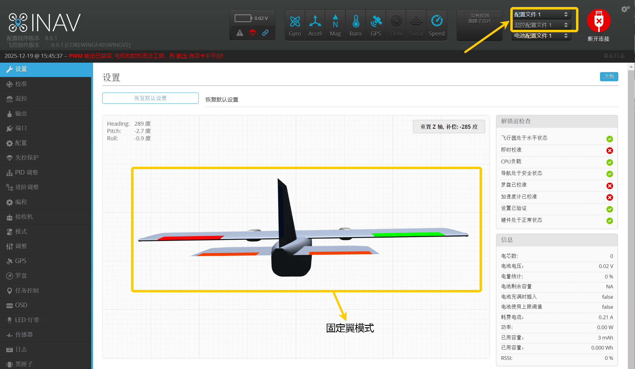
- Switch to fixed-wing mode and check if the mixer file follows Configuration File 1, Mixer Configuration File 1
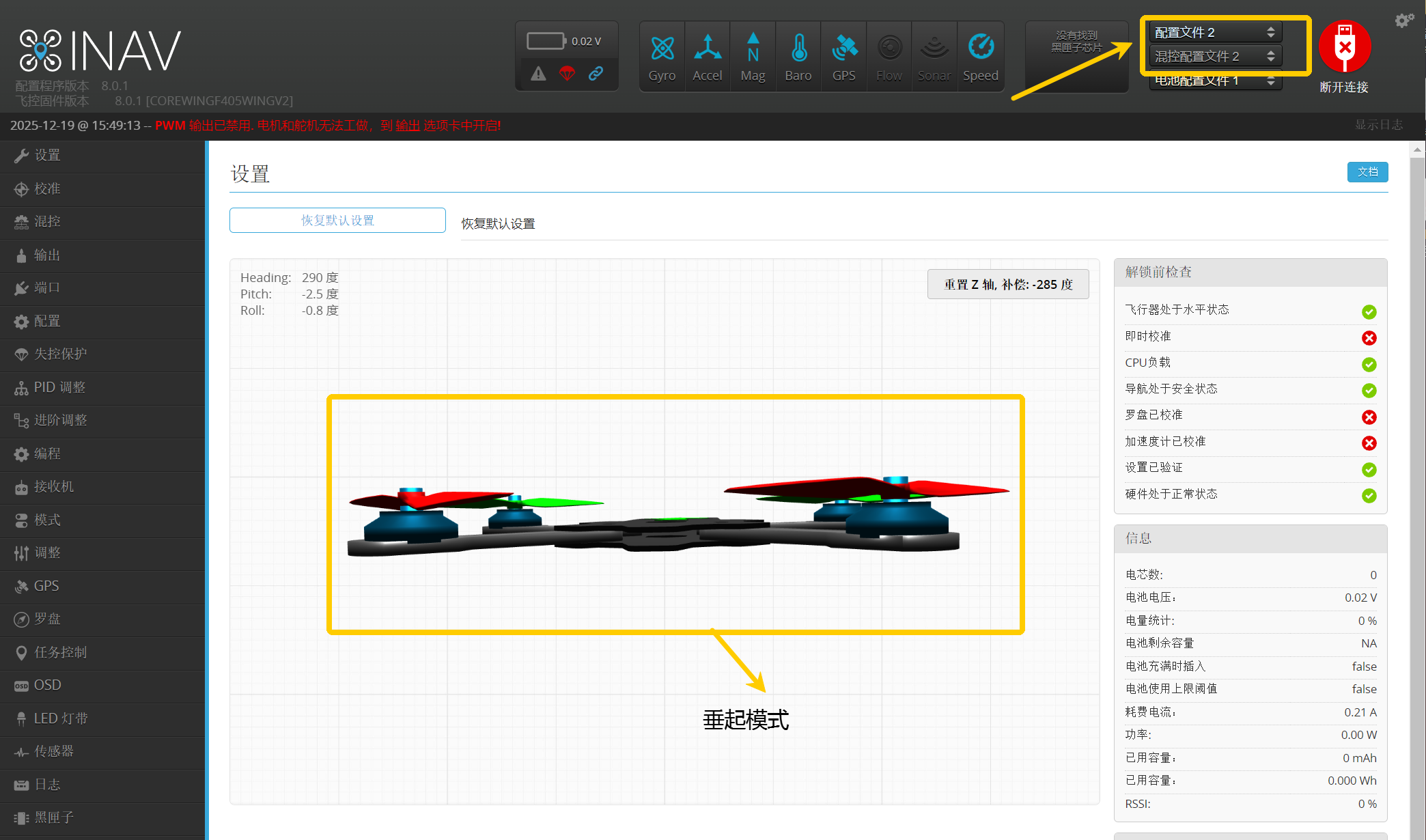
- Switch to transition mode or VTOL mode and check if the mixer file follows Configuration File 2, Mixer Configuration File 2
Important
If unable to switch configuration files via RC transmitter:
Has compass calibration been performed? Refer to section 3.3 of this article for compass calibration steps
Are MIXER PROFILE2 and MIXER TRANSITION added to flight modes? Refer to section 3.5.4 of this article for flight mode settings
Confirm if the current flight mode is Angle mode. Navigation modes that require GPS, such as altitude hold mode and position hold mode, cannot switch configuration files
Are both fixed-wing mode and multirotor mode checked for "PID configuration file will use the same index as the mixer configuration file index"? Refer to section 4.3.2 of this article for mixer and output settings
Important
When switching mixer files, you need to wait for the mixer file to load before setting its parameters, otherwise it will cause the modified parameters to not be saved successfully and the entire mixer file to be lost!!
4.3.2.2 Output Wiring
Important
The flight controller has its own BEC. If the ESC also has its own BEC, the middle power wire must be removed and insulated to prevent it from contacting conductors during flight due to vibration, causing a short circuit!!
Important
There is a bug with the S7 channel in INAV firmware. If motors are connected to S7, it will cause issues such as motors not spinning.
Important
CoreWing F405 WING V2 only supports DMA for S1-S10, S11 and S12 do not support DMA. If ESC wires are connected to S11 and S12 with Dshot protocol enabled, it will cause issues such as motors not spinning. Therefore, timer 3, timer 4, and timer 8 outputs should all be set to MOTORS, meaning motor wiring is on S1-S5.
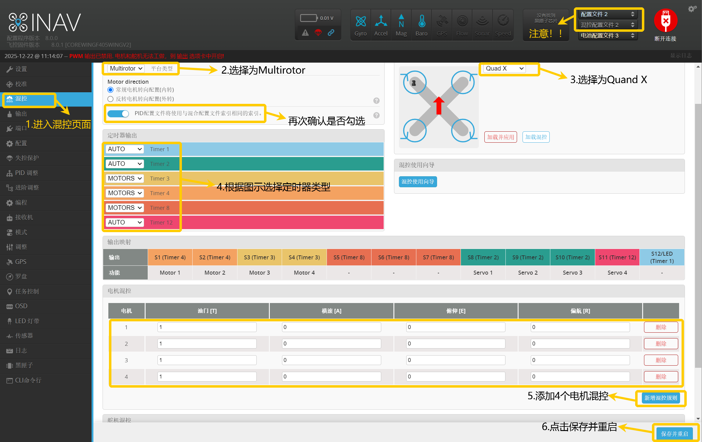
- Set Mixer Type
- Use the RC transmitter to switch to VTOL mode.
- Enter the Mixer page.
- Select Multirotor and Quad X
- Set timer mixer according to the diagram.
- Set four motor mixers according to the diagram.
- Click Save and Restart.
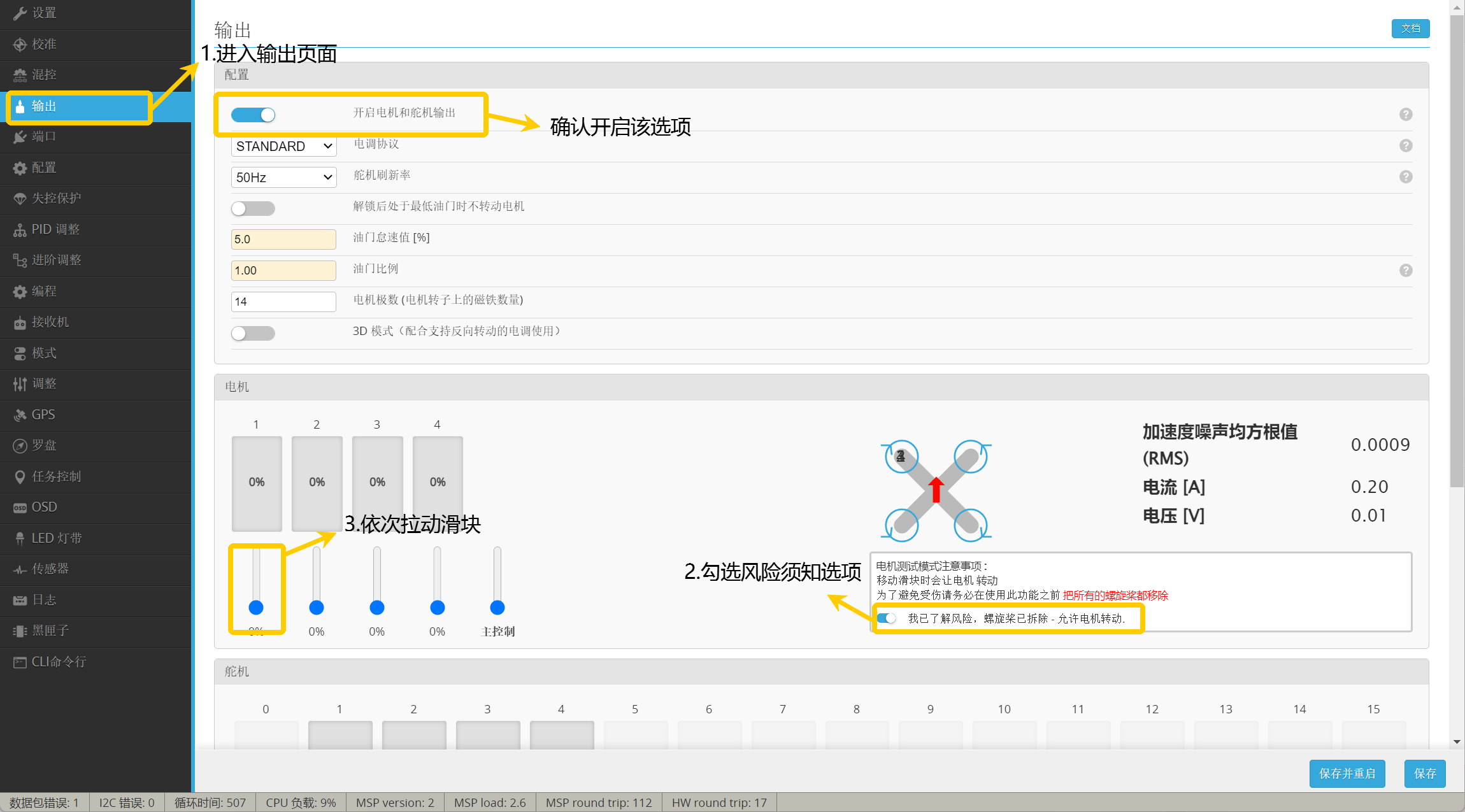
2. Confirm Motor MOTOR Number - Connect the signal wires of the four ESCs of the multirotor to S1~S4 respectively, do not connect the tail motor yet
- Connect battery power to the flight controller, enter the Output page, pull the first slider to confirm which motor is rotating. For example: the rear right motor is rotating, mark the rear right motor as MOTOR 1.
- Pull the second slider to confirm which motor is rotating. For example: the front right motor is rotating, mark the front right motor as MOTOR 2.
- Pull the third slider to confirm which motor is rotating. For example: the rear left motor is rotating, mark the rear left motor as MOTOR 3.
- Pull the fourth slider to confirm which motor is rotating. For example: the front left motor is rotating, mark the front left motor as MOTOR 4.
- After testing is complete, please disconnect the battery power
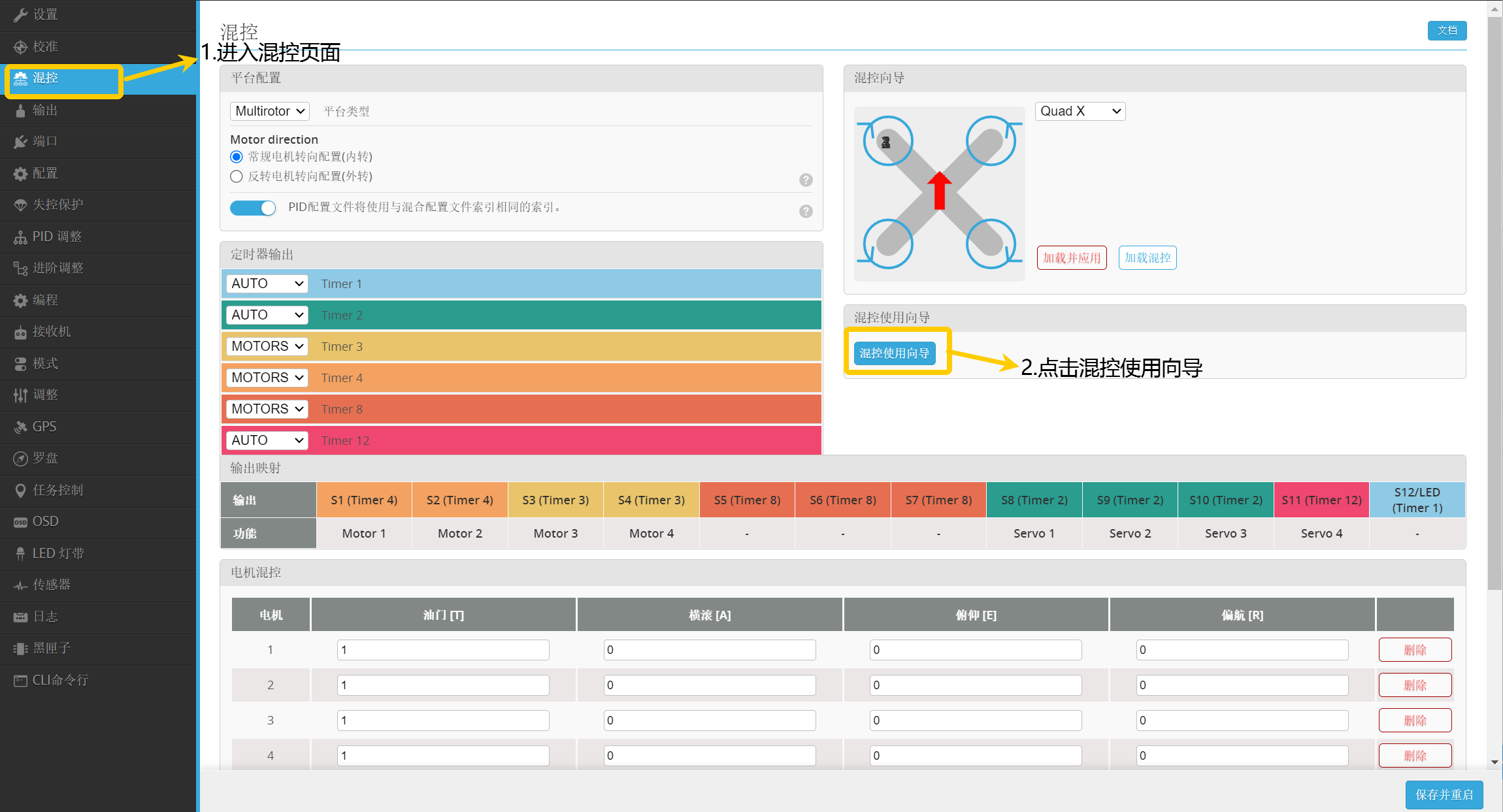
3. Set Mixer Setup Wizard - Enter the Mixer page
- Click Mixer Setup Wizard
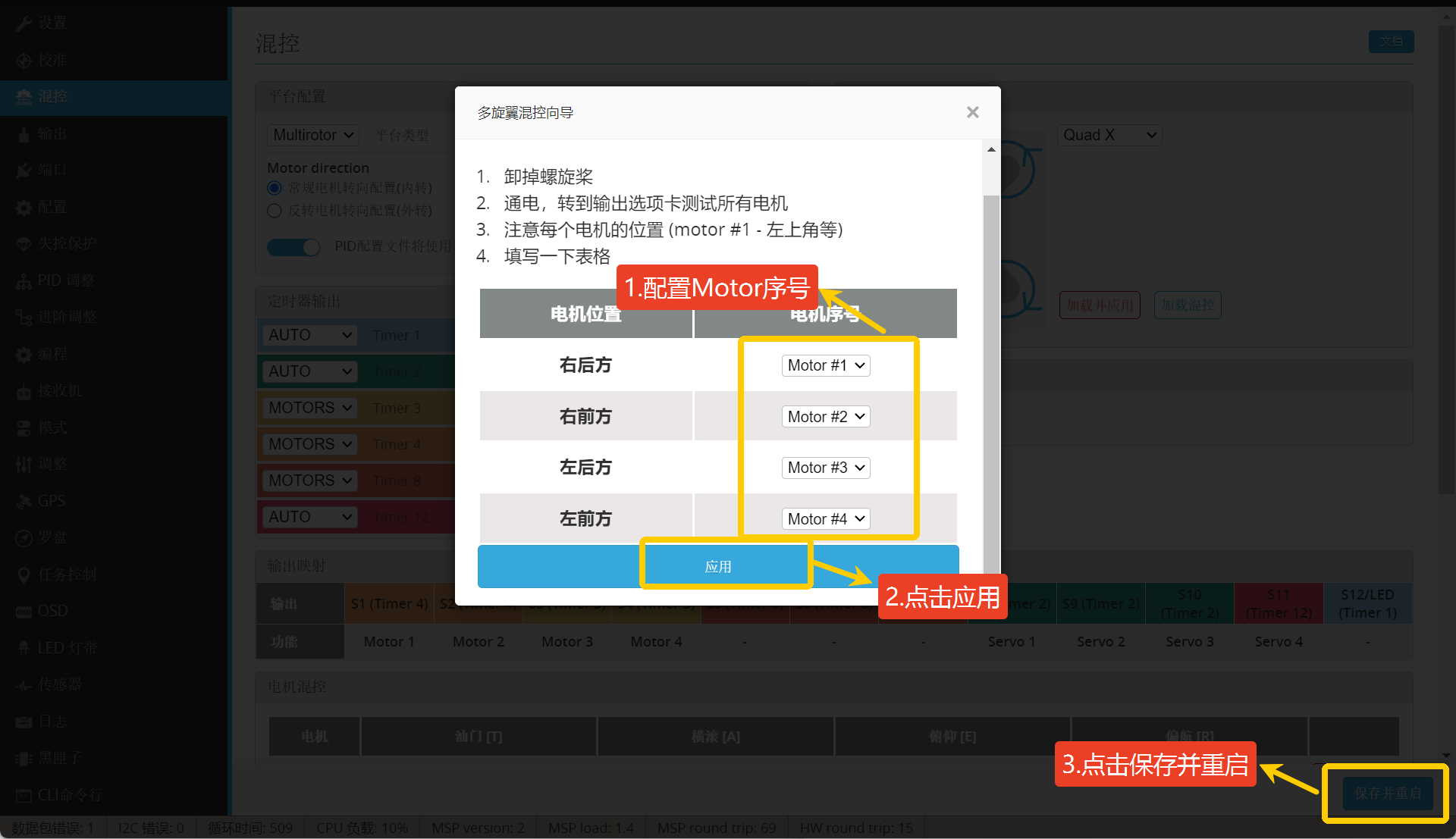
- Configure the mixer setup wizard based on the confirmed motor MOTOR numbers from the previous step. For example: Rear right motor is MOTOR 1, front right motor is MOTOR 2, rear left motor is MOTOR 3, front left motor is MOTOR 4.
- After configuration, click Apply, then click Save and Restart.
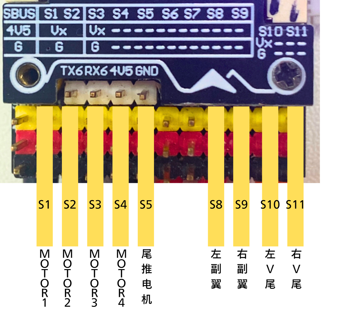
- Based on the motor definition, wiring can be done according to the following diagram.
4.3.2.3 Set VTOL Mixer File
Important
Confirm that the RC transmitter and flight controller are successfully paired
- Use the RC transmitter CH8 switch to switch to VTOL mode mixer.
- Which is Mixer Configuration File 2, PID Configuration File 2.

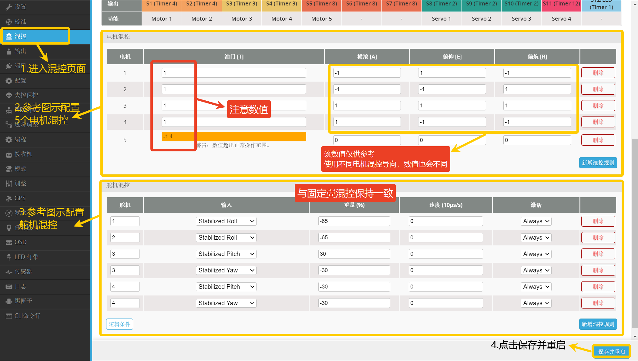
4.3.2.4 Set VTOL Motor and Servo Mixer
- Enter the Mixer page.
- Set motor mixer according to the diagram.
- Set servo mixer according to the diagram.
- Click Save and Restart.
Important
Motor throttle values must be consistent with the diagram, otherwise it will cause abnormal switching in transition mode!!
Important
Servo Mixer Description:
Servo1/Servo2 sets aileron mixing, Servo3/Servo4 sets elevator and rudder mixing. Specific settings need to be based on the aircraft model.
Important
The following Weight values are for reference only, need to be adjusted values and positive/negative signs according to actual conditions.
4.3.2.5 Set Fixed-wing Mixer File
- Use the RC transmitter CH8 switch to switch to fixed-wing mode.
- Which is Mixer Configuration File 1, PID Configuration File 1.

4.3.2.6 Set Fixed-wing Mixer Type
Important
Mixer type settings can be configured with reference to fixed-wing tutorials:
INAV Flying Wing Fixed-wing Tuning Guide: https://docs.corewing.com/plane/inav/inplaneguide/flywing-tune.html
INAV T-tail Fixed-wing Tuning Guide: https://docs.corewing.com/plane/inav/inplaneguide/t-tail-tune.html
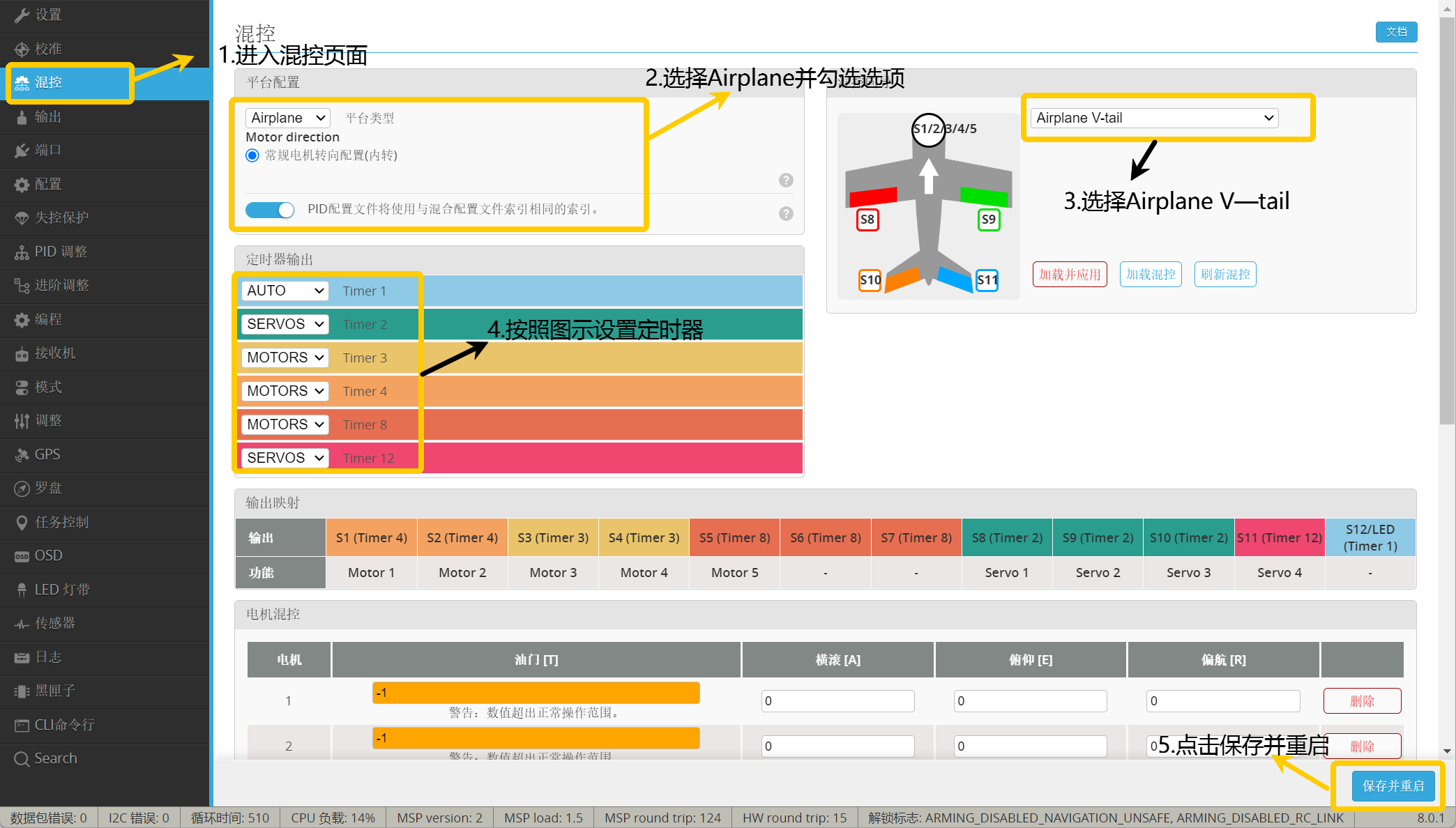
- Enter the Mixer page.
- Select Airplane and check the options.
- Select Airplane V-tail.
- Set Timer according to the diagram.
- Click Save and Restart.
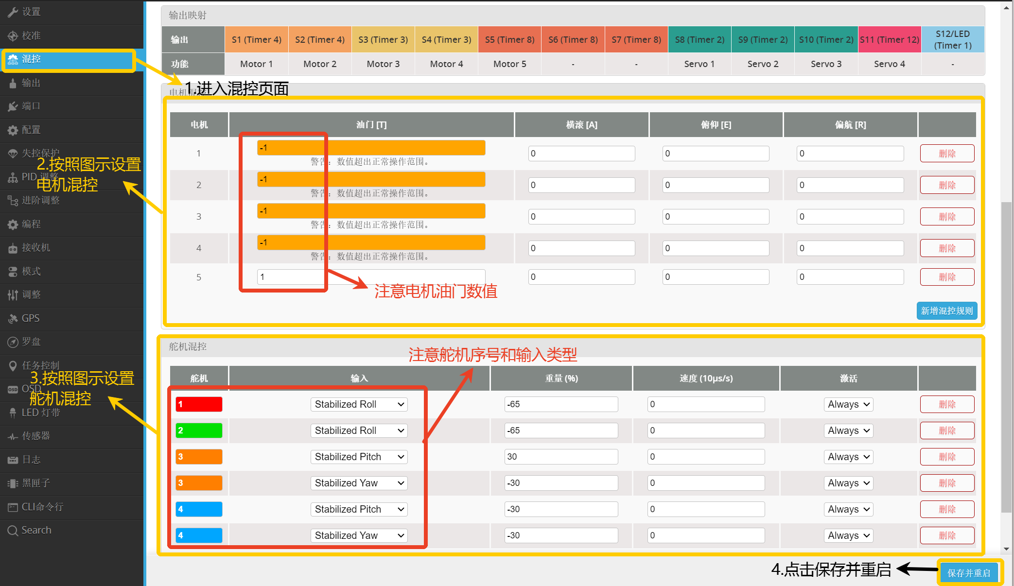
4.3.2.7 Set Fixed-wing Motor and Servo Mixer
- Enter the Mixer page.
- Set motor mixer according to the diagram.
- Set servo mixer according to the diagram.
- Click Save and Restart.
Important
Motor throttle values must be consistent with the diagram, otherwise it will cause abnormal switching in transition mode!!
Important
Servo Mixer Description:
Servo1/Servo2 sets aileron mixing, Servo3/Servo4 sets elevator and rudder mixing. Specific settings need to be based on the aircraft model.
Important
The following Weight values are for reference only, need to be adjusted values and positive/negative signs according to actual conditions.
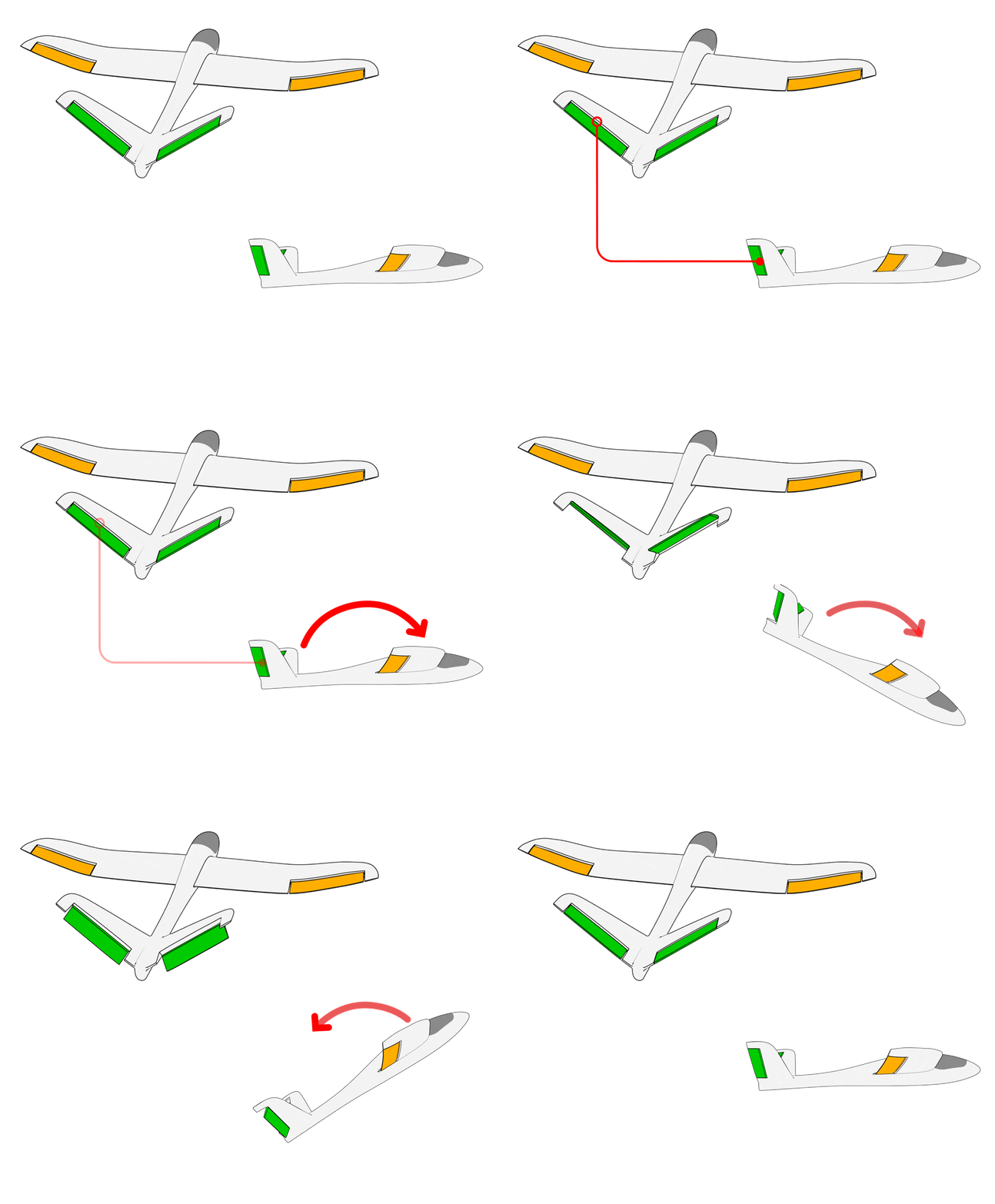
4.3.2.8 Control Surface Check
a. In stabilize mode, control surface feedback check
Important
Switch flight mode to ANGLE
- When the aircraft rolls left, the left wing control surface deflects down, and the right wing control surface deflects up.
- When the aircraft rolls right, the left wing control surface deflects up, and the right wing control surface deflects down.
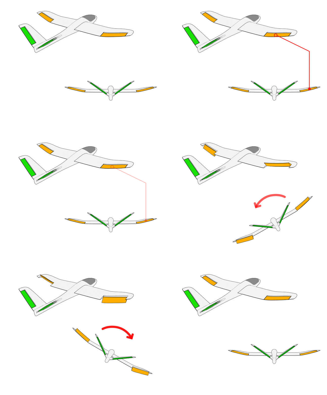
- When the aircraft pitches up, the response is both control surfaces deflecting down.
- When the aircraft pitches down, the response is both control surfaces deflecting up.
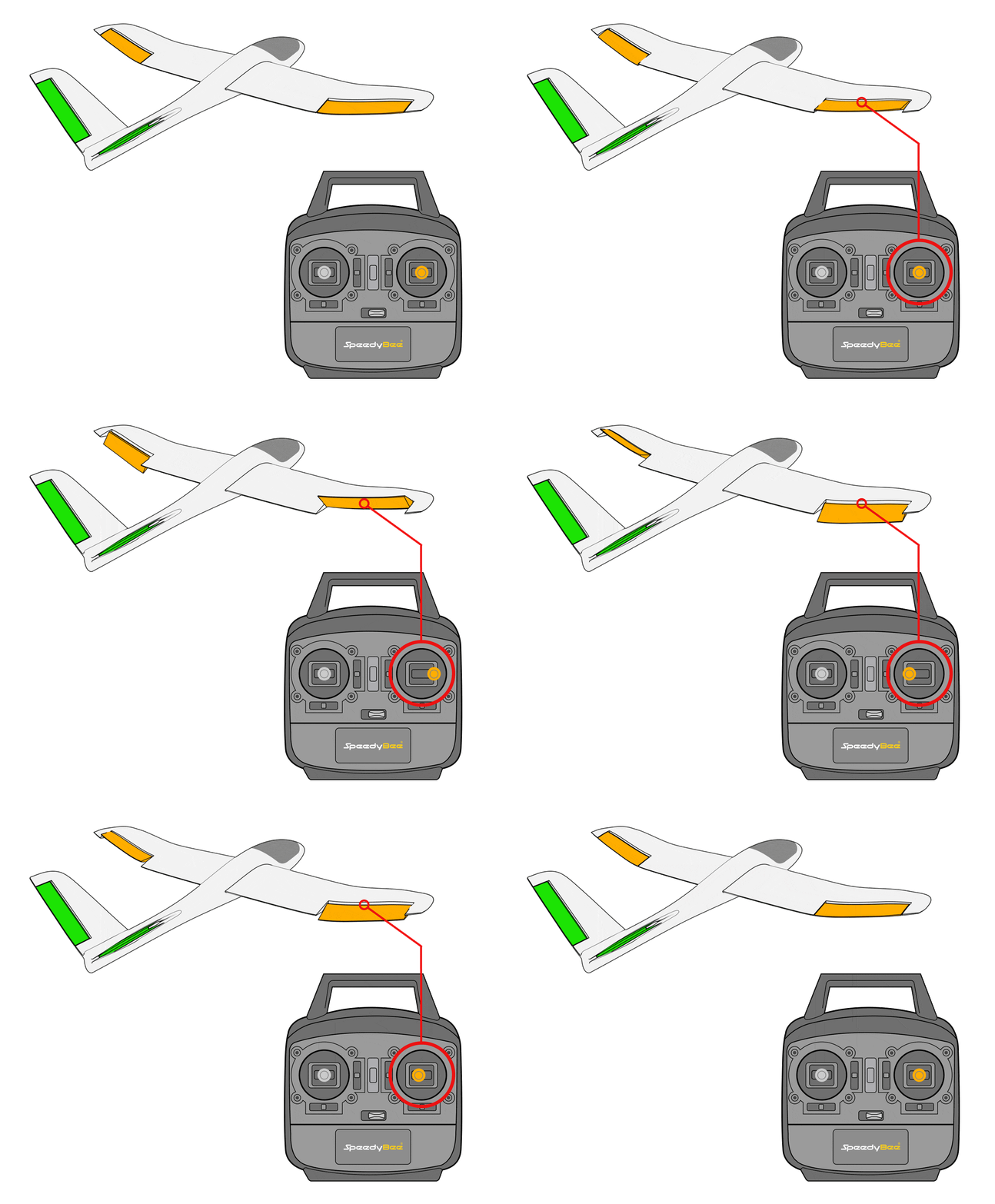
b. In manual mode, control surface feedback check
Important
Switch flight mode to ACRO
- When the aileron stick is moved left, the response is the left wing control surface deflecting up, and the right wing control surface deflecting down.
- When the aileron stick is moved right, the response is the left wing control surface deflecting down, and the right wing control surface deflecting up.
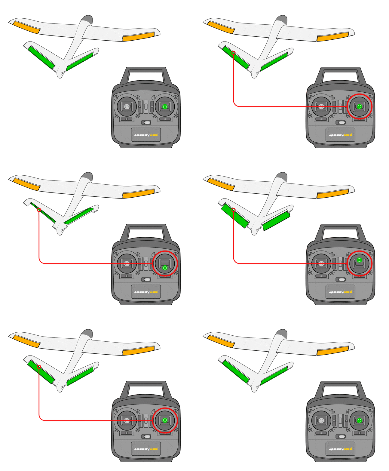
- When the elevator stick is moved up, the response is both control surfaces deflecting down.
- When the elevator stick is moved down, the response is both control surfaces deflecting up.
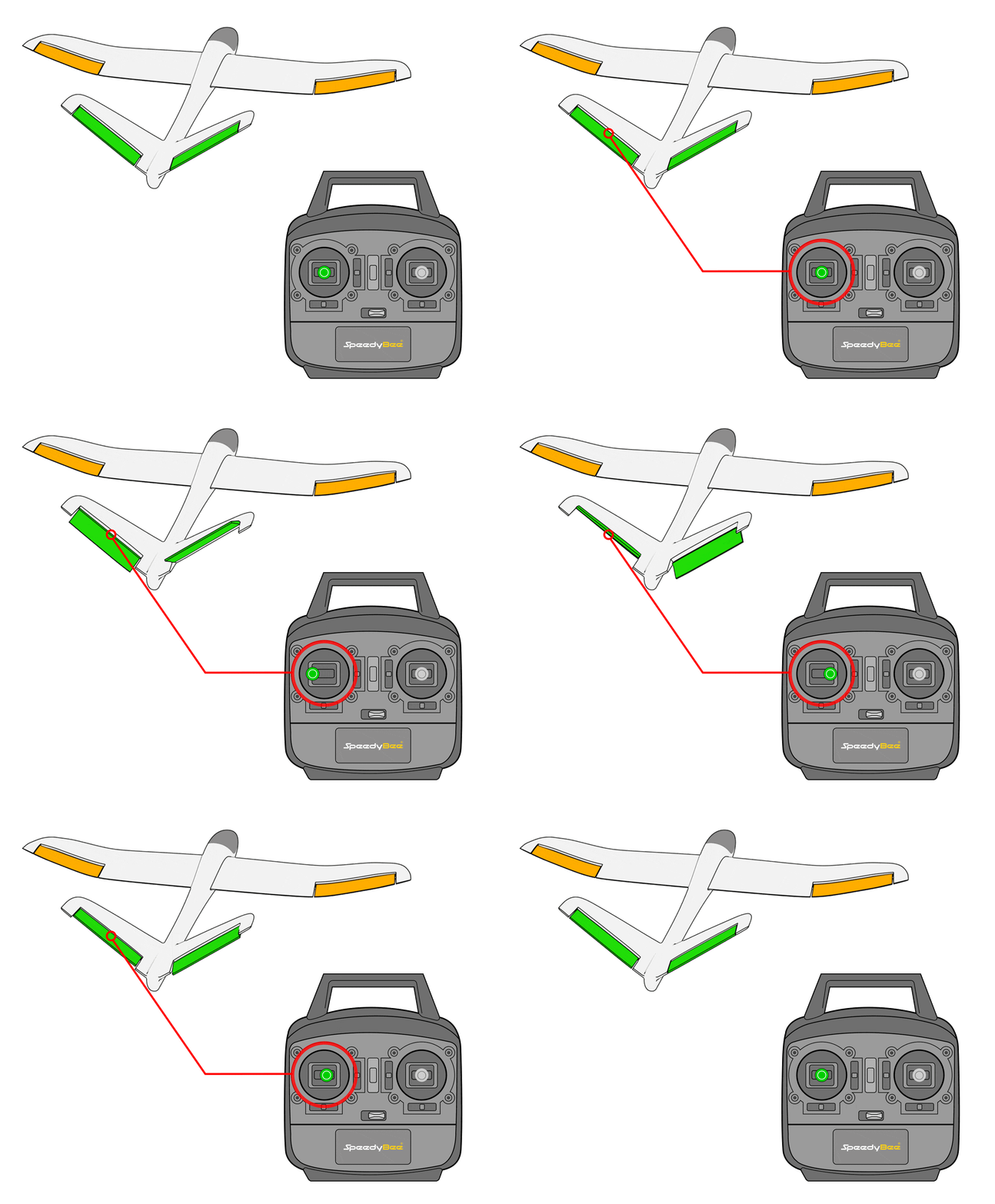
- When the rudder stick is moved left, the response is both control surfaces deflecting left.
- When the rudder stick is moved right, the response is both control surfaces deflecting right.
Important
A-tail and V-tail control surface yaw responses are consistent. When the rudder stick is moved left, the response is both control surfaces deflecting left; when the rudder stick is moved right, the response is both control surfaces deflecting right.
First check if stabilize feedback is correct. If not, add a negative sign to the Weight of the corresponding servo mixer for the incorrect control surface response, i.e., change it to a negative value.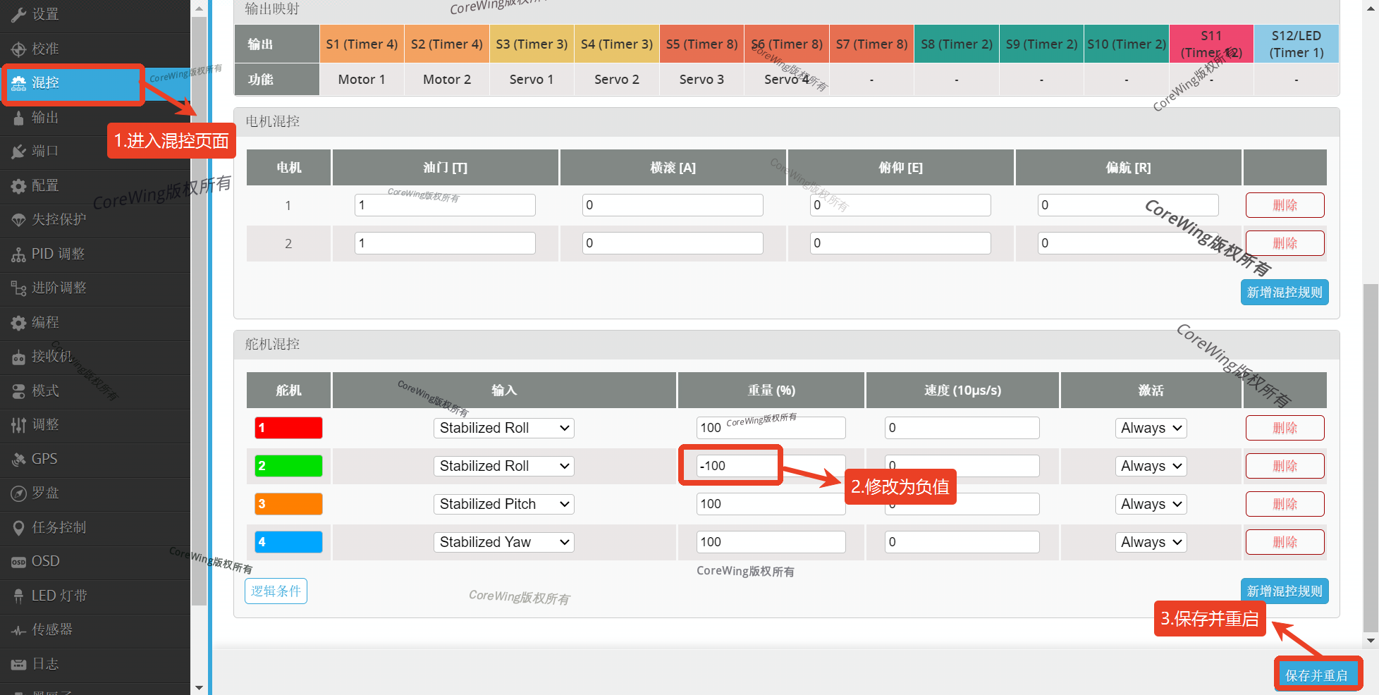
Important
Remember to modify both Mixer Profile1 and Mixer Profile2, the fixed-wing parts in both mixer configuration pages must be consistent!!
Then check if manual feedback is correct. If not, modify the RC transmitter settings.
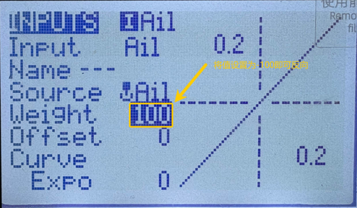
Taking an EdgeTX system RC transmitter as an example, navigate to MDL→INPUT page, set the Weight value to -100 to reverse the manual feedback.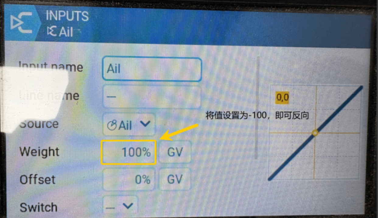
4.3.3 GPS Module Installation and Setup
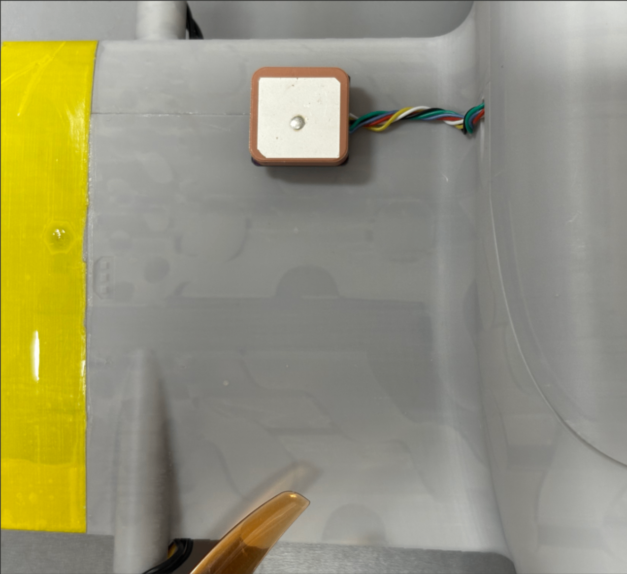
The installation position is shown in the figure. Fix the bottom of the module with 3M adhesive, ensure the module is installed securely, otherwise it will greatly affect flight performance:
Important
When installing, ensure it is mounted horizontally and vertically, do not tilt, otherwise the installation angle cannot be set correctly.
Important
For detailed content on how to install and set compass installation direction, refer to this article: https://docs.corewing.com/plane/inav/settings/gps/inav-compass-setup.html
Important
- Install away from metal objects, such as magnetic battery covers, metal pushrods, etc., otherwise it will interfere with the compass.
- Install away from receiver, servo wires, motors and other equipment, otherwise it will interfere with the compass.
- Pay attention to confirm if the installation is secure.
- For detailed installation operations of different modules, please refer to their respective manuals.
4.3.4 Video Transmitter Installation and OSD Settings
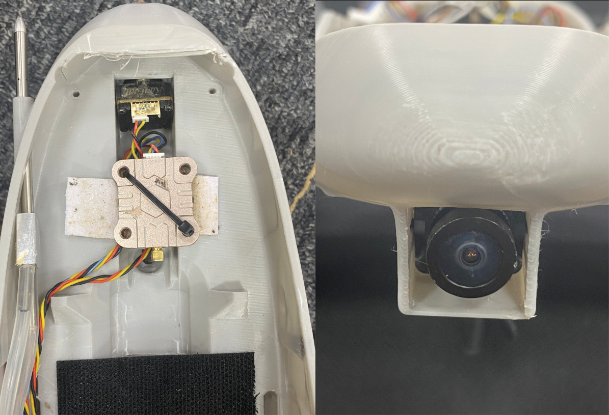
- Analog Video Transmitter Installation:
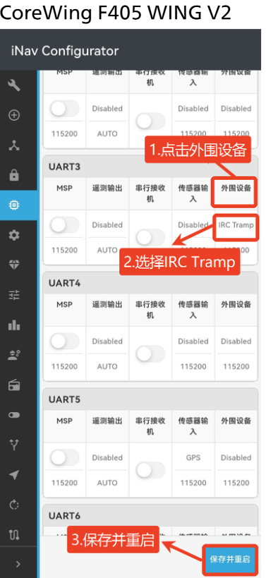
- Analog Video Transmitter Parameter Settings:
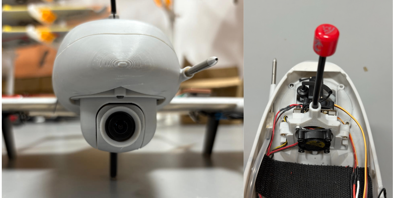
- HD Video Transmitter Installation:
- HD Video Transmitter Parameter Settings:
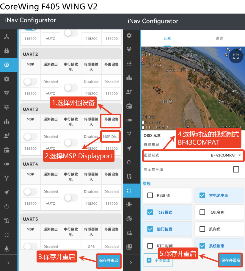
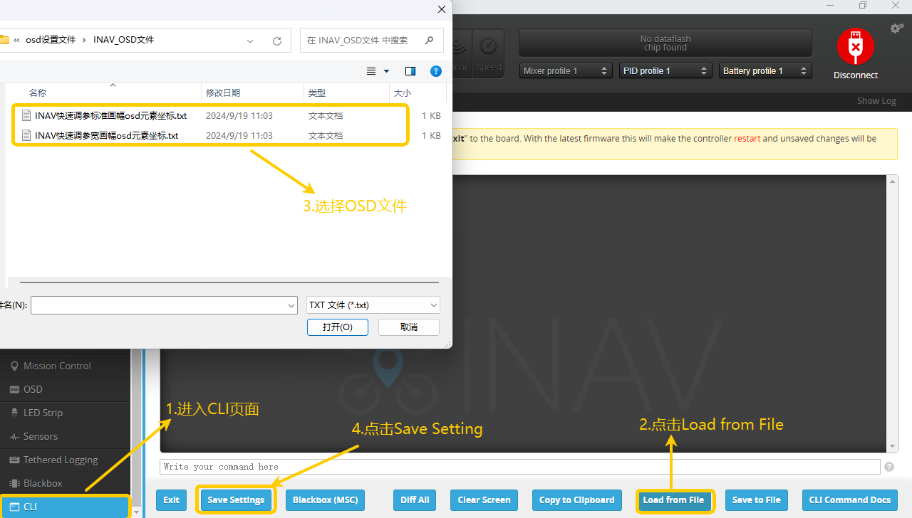
OSD Settings: - OSD Configuration File: https://oss.corewing.com/knowledge/INAV_OSD.zip
Can be downloaded and imported directly for use. - Enter the CLI page.
- Click Load from File.
- Select the OSD file.
- Wait for import to complete.
- Click Save Setting.
4.3.5 Airspeed Sensor Installation and Setup
Airspeed sensor installation location reference: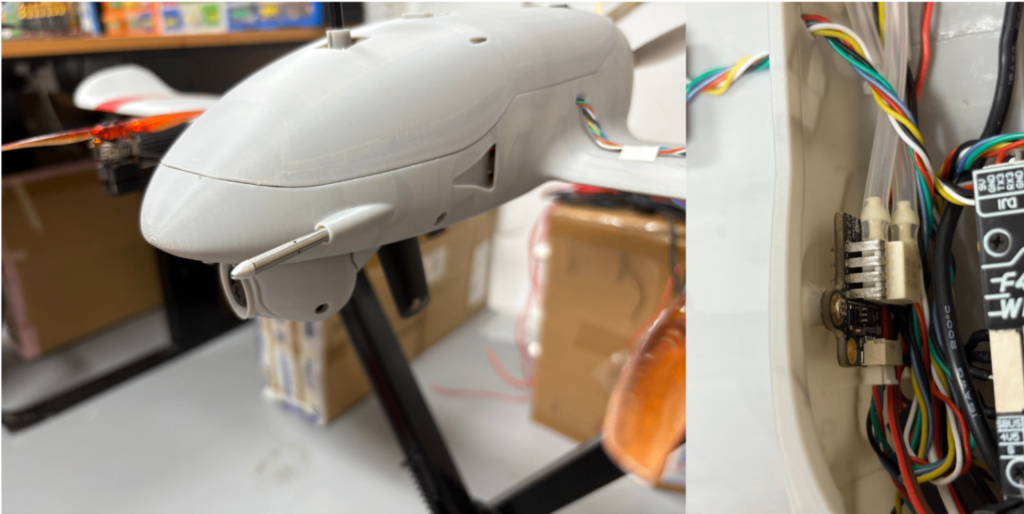
Important
For detailed content on airspeed sensor installation, parameter settings, and calibration, refer to this article: https://docs.corewing.com/plane/inav/settings/airspeed/setup.html
V. Pre-flight Debugging
5.1 RTH Parameter Settings
Important
For detailed information on how to set up Return-to-Home (RTH) mode, please refer to: https://docs.corewing.com/plane/inav/settings/fc/rth-setup.html
5.2 ESC Calibration
Important
Ensure the battery is disconnected and propellers are removed!
① Enter the Output page.
② Check the risk acknowledgment option.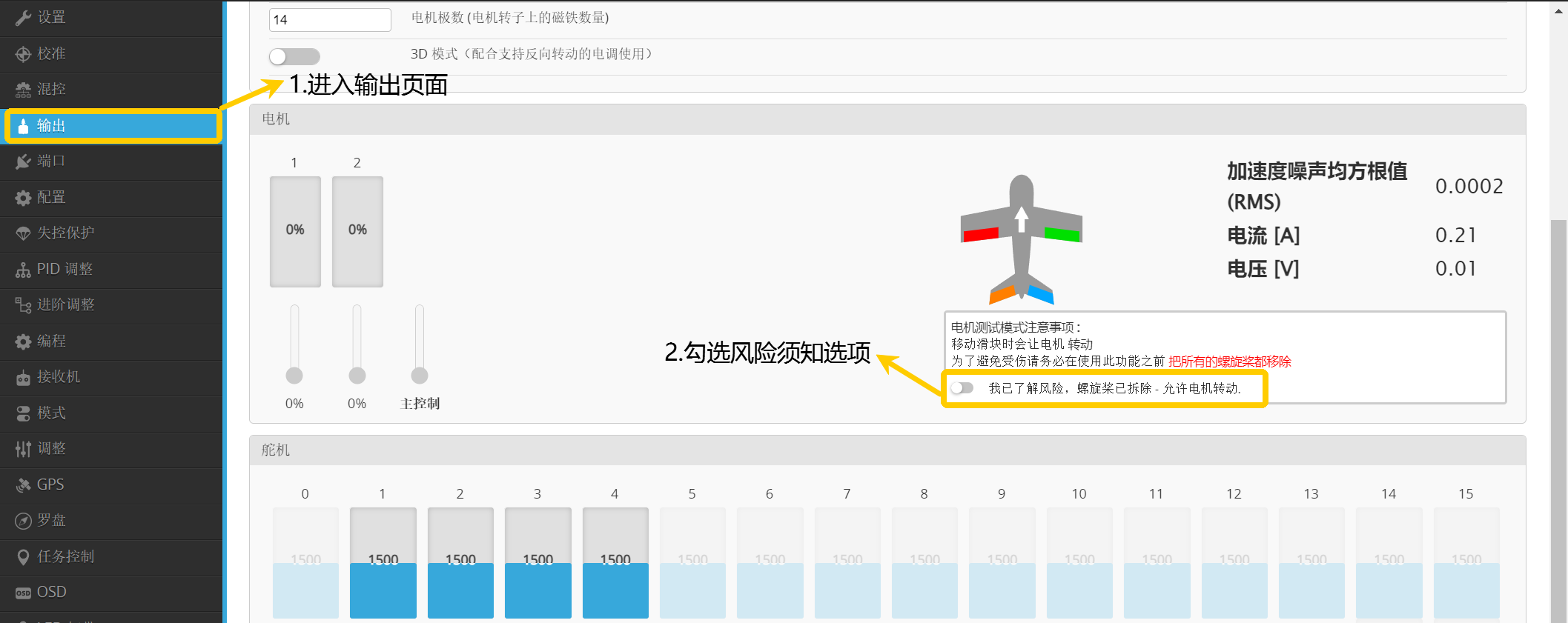
③ Immediately push the Main Control to 100%.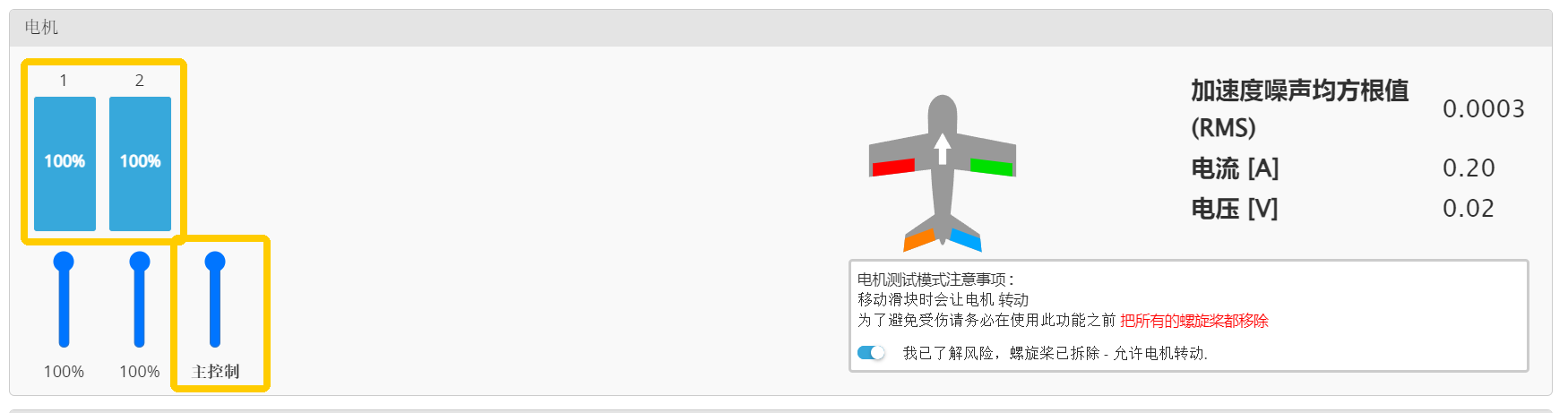
④ Power the flight controller with the battery.
⑤ The ESC will beep → immediately push the Main Control to 0% → the ESC beeping will stop.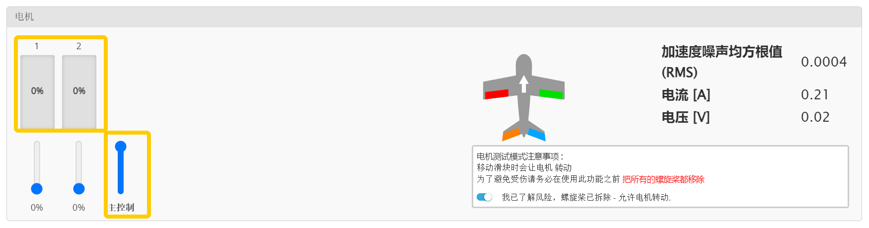
BLHeli32/BLHeli_S ESC Calibration Sounds: Connect the battery and wait 2 seconds → "playing a song" is the throttle maximum confirmation tone → wait for the song to finish → push the throttle to minimum and wait 1 second → "playing another song, dee-dee" is the throttle minimum confirmation tone → calibration complete
PWM ESC Calibration Sounds: Connect the battery and wait 2 seconds → "beep-beep" is the throttle maximum confirmation tone → push the throttle to minimum and wait 1 second, N short beeps indicate the number of LiPo cells → "beep" is the throttle minimum confirmation tone → calibration complete
⑥ Gently push the throttle, the motors should start immediately. Push the throttle from 0% to 20% and check if the response is linear.
⑦ If the result differs from the above, disconnect the battery and return to step ② to recalibrate.
Important
For detailed information on enabling Dshot protocol, please refer to this article: https://docs.corewing.com/plane/inav/settings/esc/esc-calib-dshot.html
5.3 Motor Direction Check
Important
Use a battery to power the flight controller
Important
CH5 is used for arming/disarmingCH8 is used to switch aircraft modes, the first segment is Fixed-wing mode, the second segment is Transition mode, and the third segment is VTOL mode.CH9 is used to switch flight modes in VTOL state, the first segment is ANGLE (VTOL self-leveling), the second segment is NAV LOITER (position hold) combined with NAV ALTHOLD (altitude hold), and the third segment is NAV ALTHOLD (altitude hold).
Important
How to force arm: https://docs.corewing.com/plane/inav/settings/fc/force-arm.html
- Switch the transmitter dial to VTOL mode, switch flight mode to ANGLE, force arm, and the four rotor motors will immediately start idling
Important
The throttle idle value remains at the default of 5.
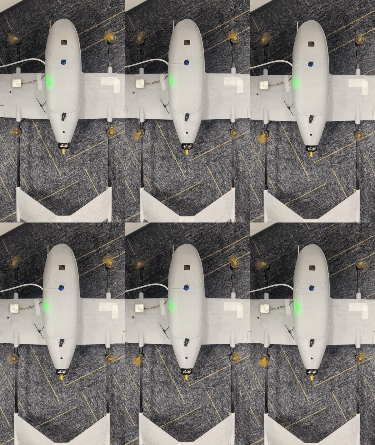
- Then switch to transition mode, and the four rotor motors and the tail pusher motor will immediately start rotating
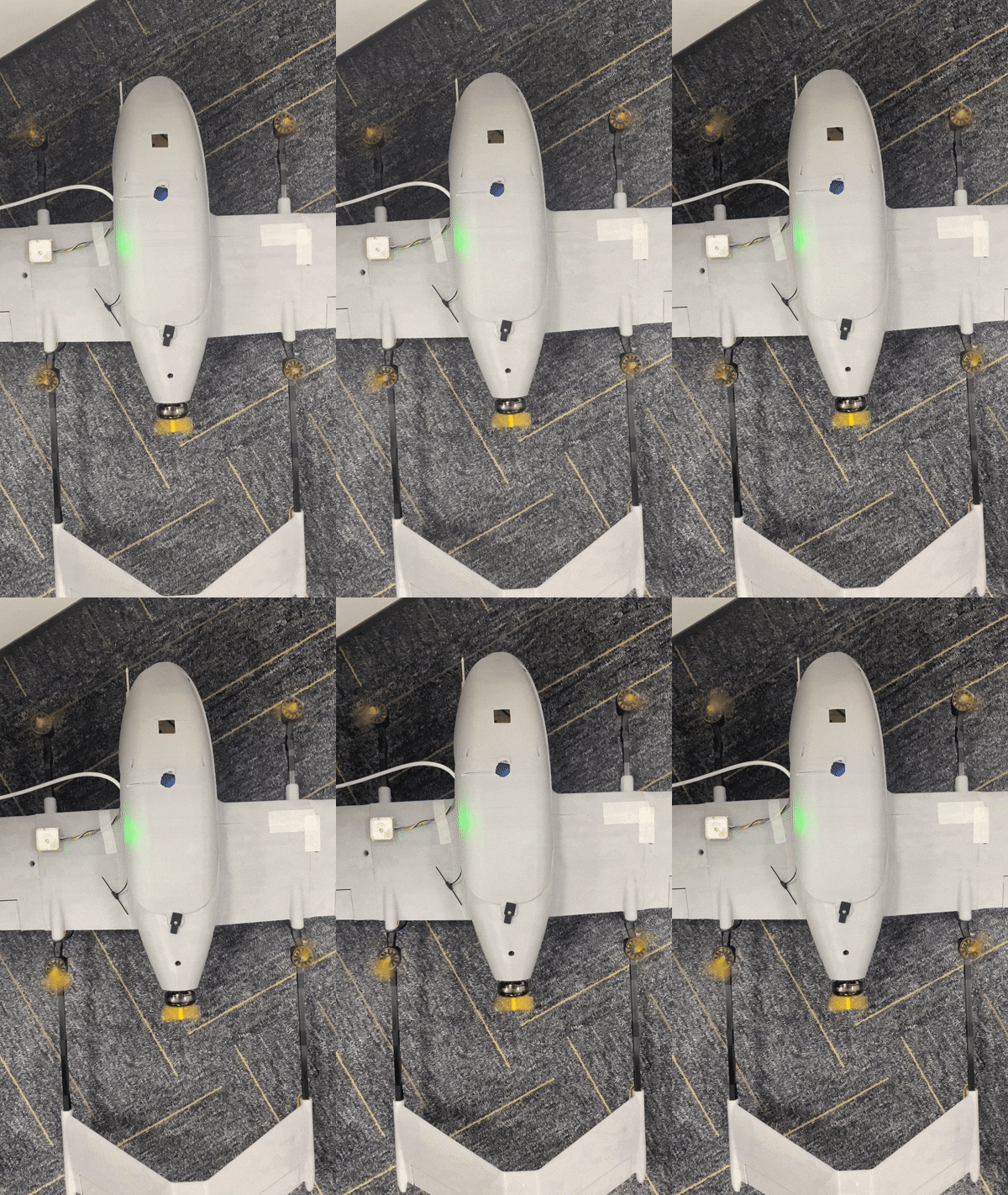
- Finally switch to fixed-wing mode, gently push the throttle, and only the tail pusher motor will rotate
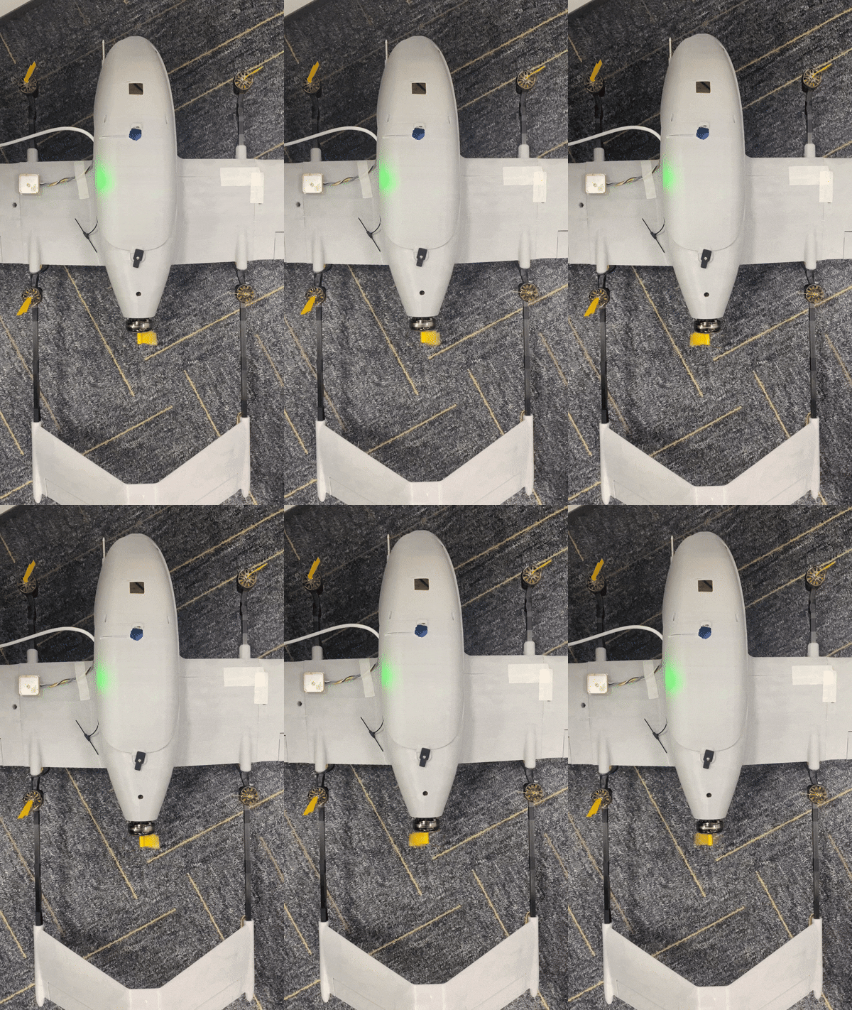
Important
If the motor rotation direction is incorrect:
- Please check if the motor mixing in the mixing page is set correctly, and verify that the tail pusher motor mixing is also set correctly. Refer to section 4.3.2.4 Setting VTOL motor and servo mixing and section 4.3.2.7 Fixed-wing motor and servo mixing of this document.
- In the fixed-wing mode output page, is enabled the option to not rotate motors at minimum throttle after arming? In the VTOL mode output page, is disabled the option to not rotate motors at minimum throttle after arming? Refer to section 4.3.2 Mixing and output settings of this document.
- Check if there are poor connections in the ESC wiring.
- Gently push the throttle, the correct motor rotation direction should be front-left motor clockwise, front-right motor counter-clockwise, rear-left motor counter-clockwise, rear-right motor clockwise, tail pusher motor direction not specified. As shown in the figure below, you can gently touch the motors to feel the rotation direction.
Important
If the motor rotation direction is incorrect, swap any two of the three motor wires for any motor to adjust the direction.
Important
You can also change motor direction through ESC settings: https://docs.corewing.com/plane/inav/settings/esc/how-to-set-motor-reversal-via-esc-calibration-inav-firmware.html

5.3.1 RC Transmitter Output Check
Force arm → gently push the throttle until motors just start rotating → all motors rotate → give slight stick inputs to send commands to the flight controller.
Important
For detailed information on how to force arm, please refer to this article: https://docs.corewing.com/plane/inav/settings/fc/force-arm.html
Important
You can feel the motor speed by attaching tape or masking tape.
- Push the pitch stick, rear-left and rear-right motor speeds increase, front-left and front-right motor speeds decrease;
- Pull the pitch stick, front-left and front-right motor speeds increase, rear-left and rear-right motor speeds decrease;
- Roll left, front-right and rear-right motor speeds increase, front-left and rear-left motor speeds decrease;
- Roll right, front-left and rear-left motor speeds increase, front-right and rear-right motor speeds decrease;
If the feedback is inconsistent, please check the output page and pin header connections.
5.3.2 Motor Self-Stabilization Feedback Check
Force arm → gently push the throttle until motors just start rotating → all motors rotate → give the aircraft some attitude changes.
Important
You can feel the motor speed by attaching tape or masking tape.
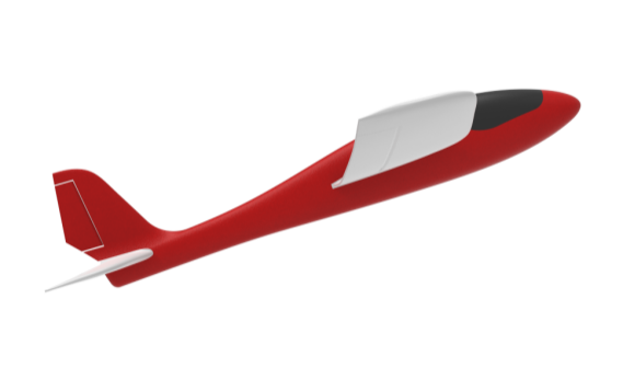
- When the aircraft pitches up, rear-left and rear-right motor speeds increase;
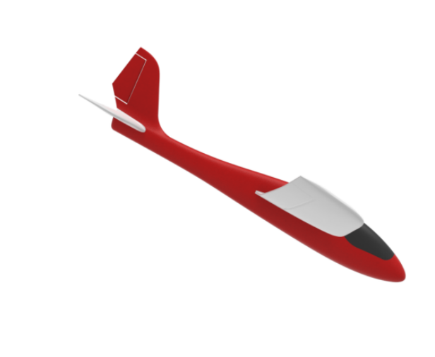
- When the aircraft pitches down, front-left and front-right motor speeds increase;
- When the aircraft rolls left, front-left and rear-left motor speeds increase;
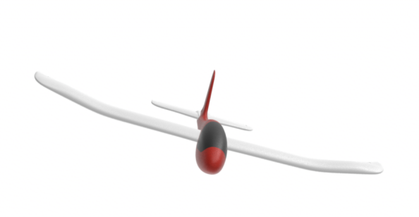
- When the aircraft rolls right, front-right and rear-right motor speeds increase;
If the motor feedback does not match the above, please check the output page and pin header connections.
5.3.3 Propeller Installation
- Choose between standard or reverse-pitch propellers based on motor rotation direction.
- When installing propellers, ensure the side with text is facing upward.
Multirotor propeller installation: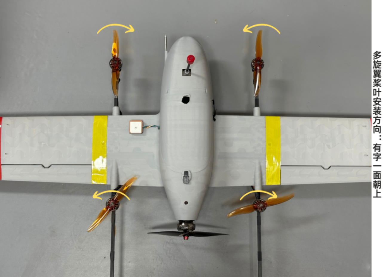
Tail pusher motor propeller installation: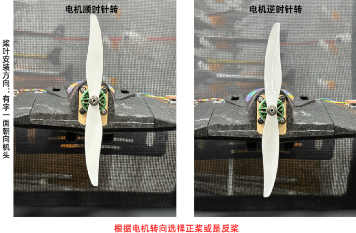
To counteract motor torque, you can adjust the control surfaces using the following method: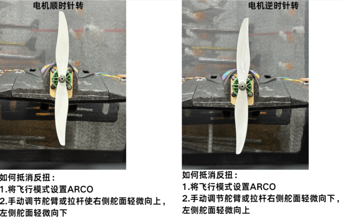
5.4 Compass Calibration
Important
Please confirm the compass installation direction before calibration!
How to confirm compass direction: https://docs.corewing.com/plane/inav/settings/gps/inav-compass-setup.html
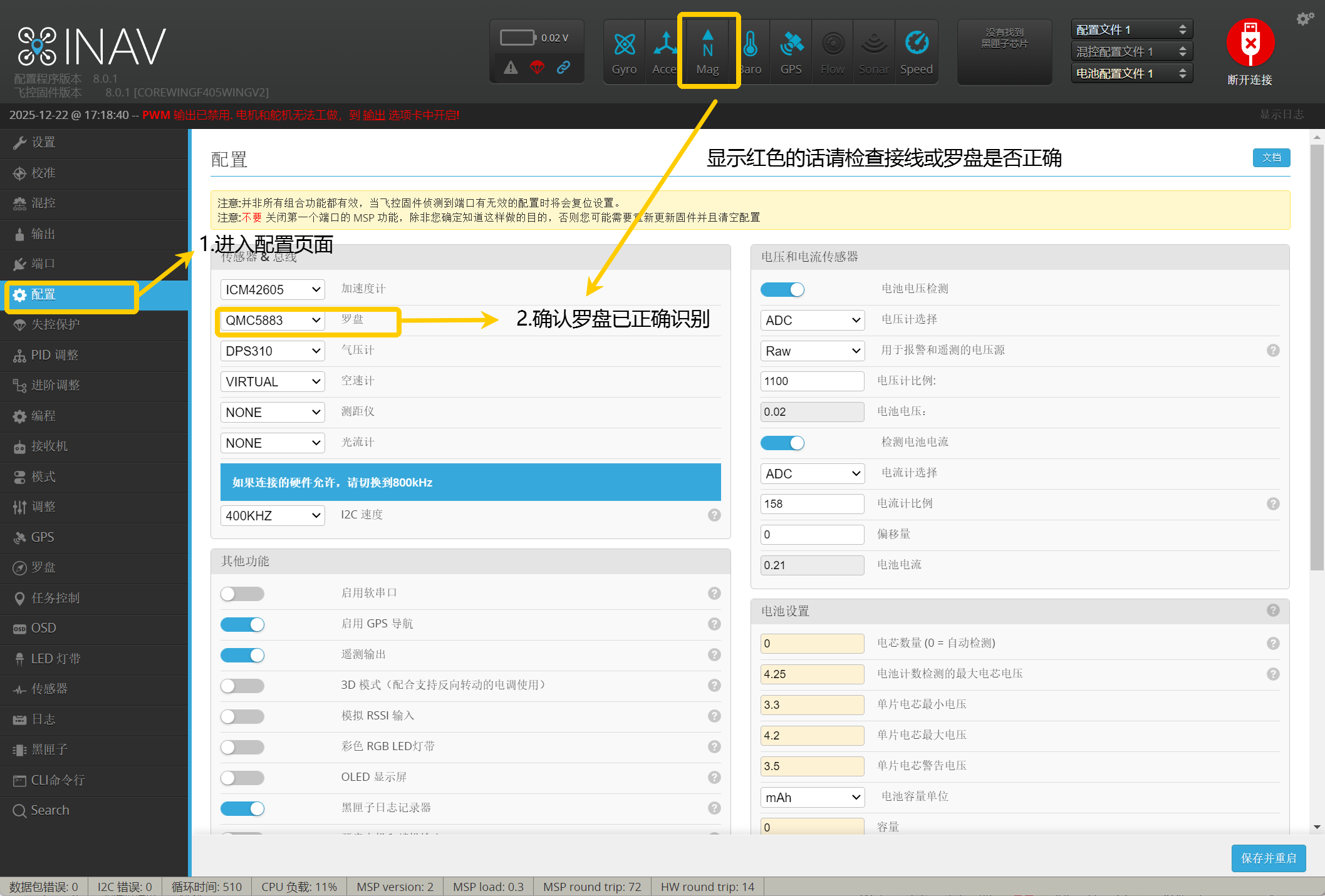
- Enter the Configuration page.
- Select Auto for automatic recognition, ensure the compass is correctly identified.
Important
If the compass icon is red, it means it was not correctly identified. Please check the wiring or if the compass is working properly!
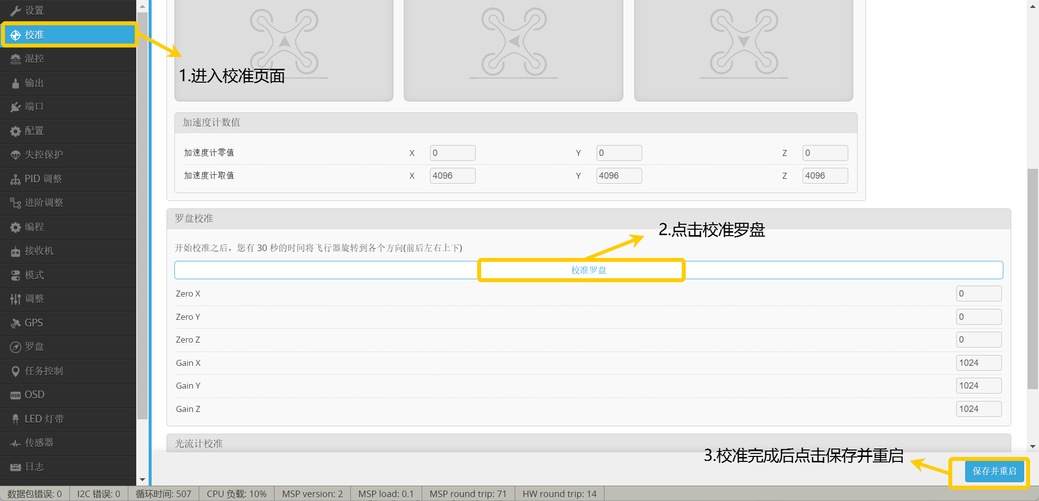
- Enter the Calibration page.
- Click Calibrate Compass.
- Within 30 seconds, rotate the aircraft 360° along each axis.
5.5 Lost Link Protection Parameter Settings
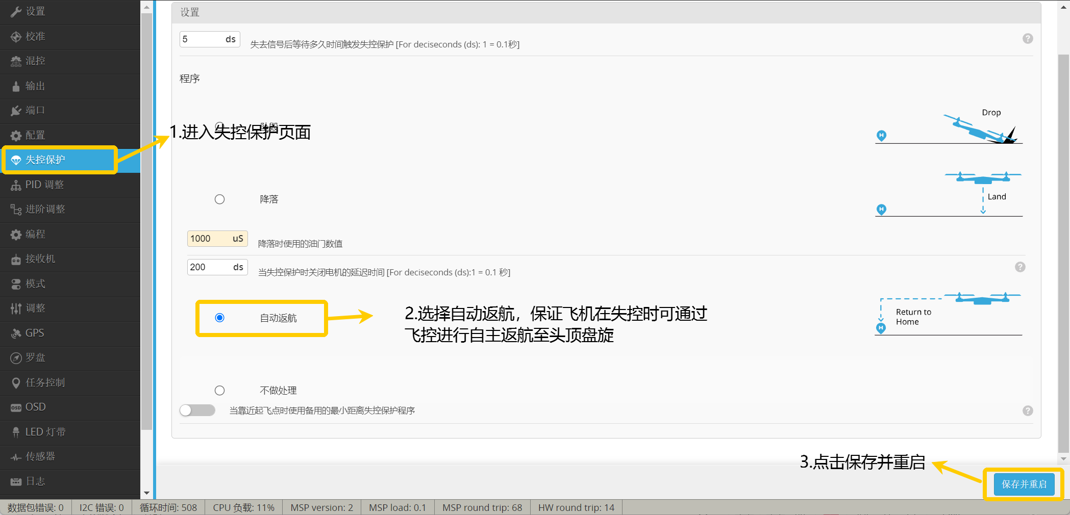
- Enter the Lost Link Protection page.
- Select
RTHto ensure the aircraft can autonomously return to home and circle above when connection is lost. - Click Save and Restart.
- Switch the transmitter switch to fixed-wing mode
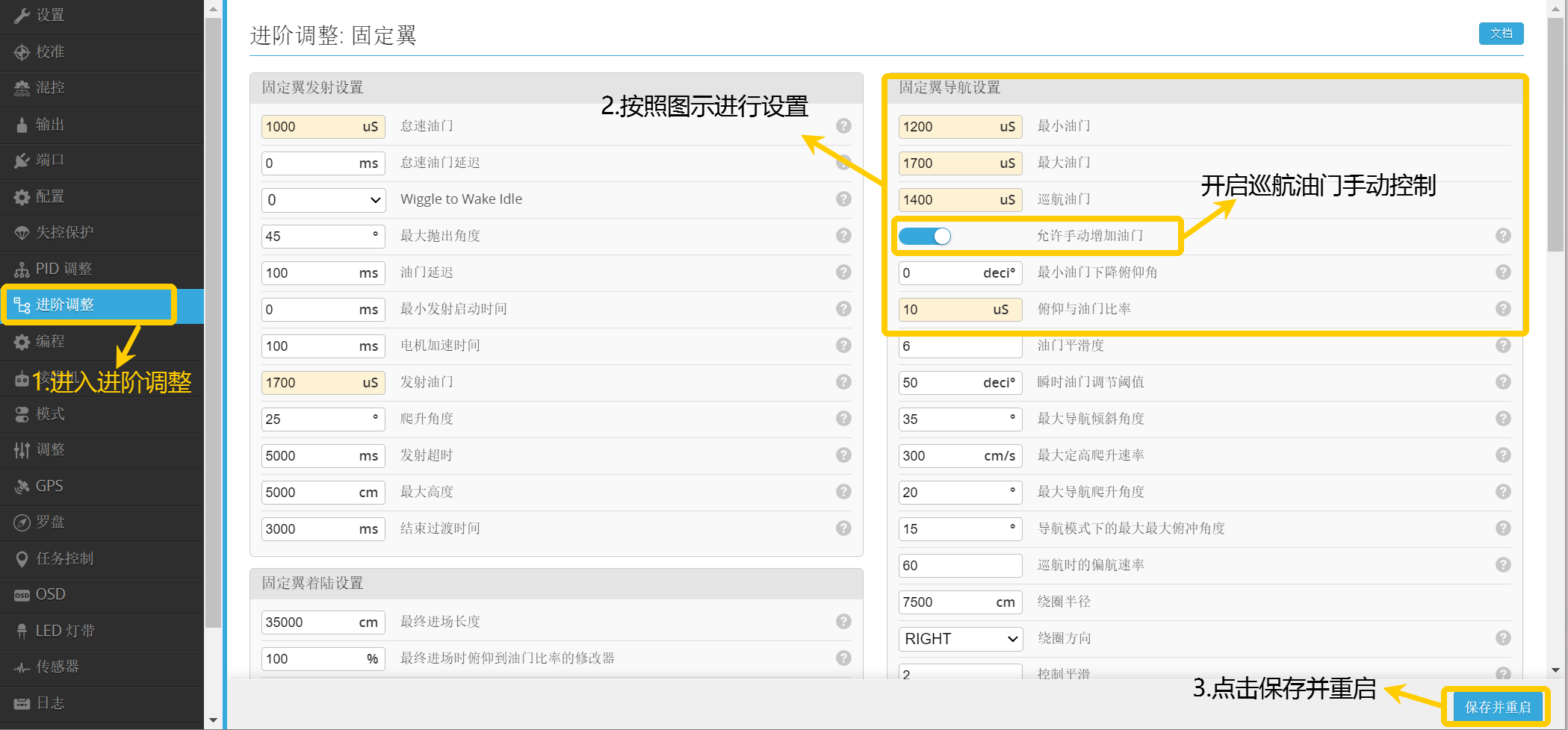
- Click Advanced Tuning.
- Configure according to the diagram.
- Note that the parameters in the red box need to be set to
NEVER.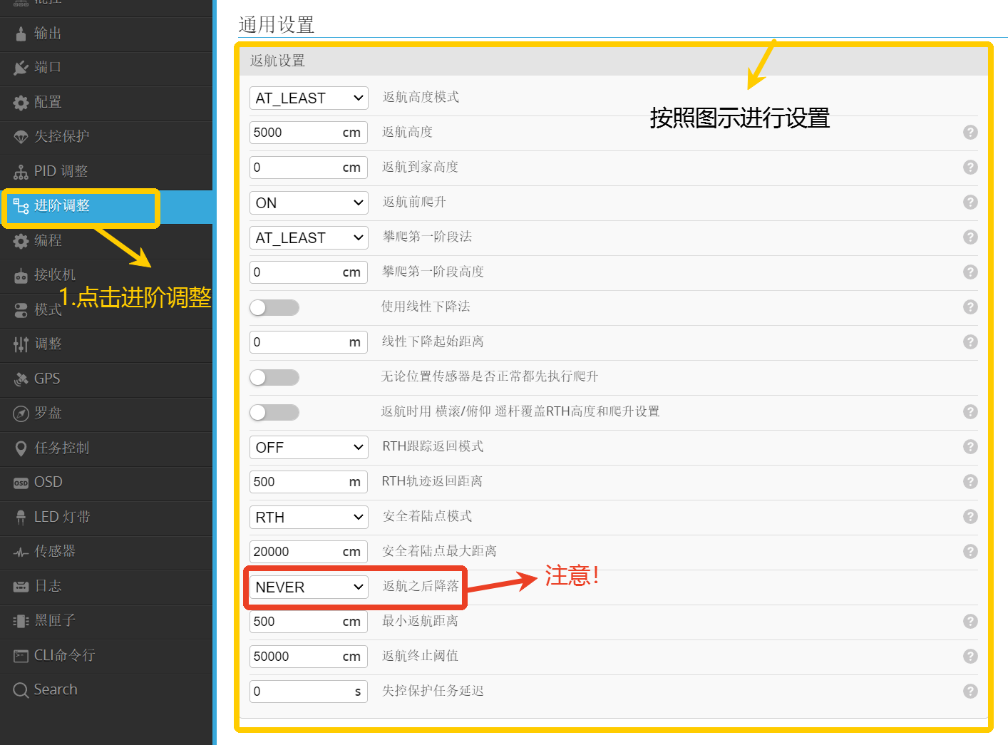
Important
After completing the settings, remember to click Save and Restart.
- Switch the transmitter switch to fixed-wing mode
- Click Advanced Tuning.
- You can configure according to the diagram, adjust the fixed-wing cruise throttle based on actual conditions.
- Click Save and Restart.
Important
It is recommended that during the first return-to-home, enter the Advanced Tuning option to allow manual throttle increase to avoid the default return speed being too low, preventing accidents.
6. Flight Testing
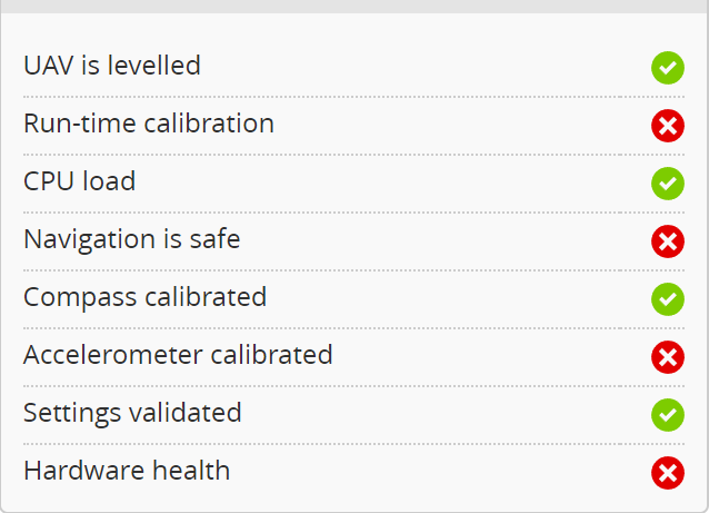
6.1 Pre-flight Parameter Check
Important
For detailed solutions to common arming issues, please refer to this article: https://docs.corewing.com/plane/inav/settings/fc/fcproblem/unlock-fail-common.html
6.2 Pre-flight Inspection
6.2.1 Center of Gravity Check
1. Reference aircraft markings:
- Many flying wing or fixed-wing aircraft have recommended center of gravity positions marked on the fuselage, typically at 25-30% back from the leading edge of the main wing.
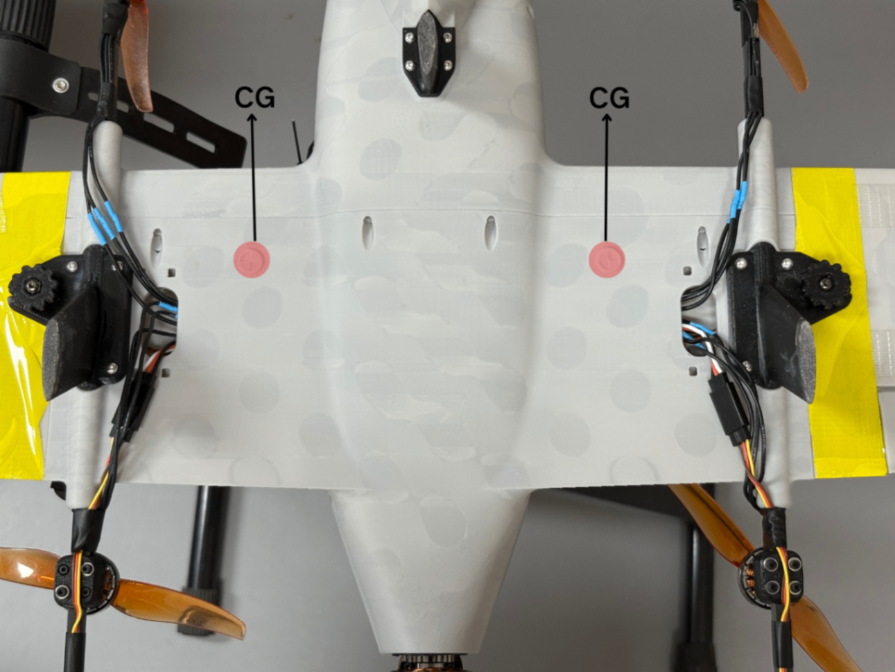
2. Finger support method: - Place the aircraft on two fingers at the recommended center of gravity point under the main wing and balance the fuselage gently.
- If the nose is too heavy or tail is too heavy, adjust the battery or add ballast.
Nose heavy (center of gravity too forward):
- The aircraft will have difficulty climbing during flight, which may lead to a crash.
- Try moving the battery backward or reducing nose ballast.
Tail heavy (center of gravity too aft):
- The aircraft is prone to stalling on climb.
- Solution: move the battery forward or add nose ballast.
6.2.2 Pre-flight Control Surface Check
Important
Switch flight mode to ANGLE
- When the aircraft rolls left, the left wing control surface deflects down, and the right wing control surface deflects up.
- When the aircraft rolls right, the left wing control surface deflects up, and the right wing control surface deflects down.
- When the aircraft pitches up, the response is both V-tail control surfaces deflecting down simultaneously.
- When the aircraft pitches down, the response is both V-tail control surfaces deflecting up simultaneously.
Important
Switch flight mode to ACRO
- When the aileron stick is moved left, the response is the left wing control surface deflecting up and the right wing control surface deflecting down.
- When the aileron stick is moved right, the response is the left wing control surface deflecting down and the right wing control surface deflecting up.
- When the elevator stick is moved up, the response is both V-tail control surfaces deflecting down simultaneously.
- When the elevator stick is moved down, the response is both V-tail control surfaces deflecting up simultaneously.
- When the rudder stick is moved left, the response is both V-tail control surfaces deflecting left simultaneously.
- When the rudder stick is moved right, the response is both V-tail control surfaces deflecting right simultaneously.
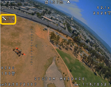
6.2.3 Satellite Number Check
Important
Outdoors, check if the satellite number is greater than 8. Only take off when it's greater than 8!
If the satellite count remains below 8, move to an open area. If there's no improvement, replace the GPS module.
6.2.4 Wind Direction Confirmation
- Observe wind direction:
- Observe wind indicators such as smoke, wind vanes, flags.
- Use light objects (like grass leaves) tossed into the air to observe their drift direction.
- Determine upwind takeoff direction:
- Taking off into the wind provides more lift and reduces takeoff speed requirements.
- Taking off downwind may cause stalling or the nose being pushed down by the wind, easily leading to a crash.
6.3 Flight Testing
Important
Flight mode effects:CH8 is used to switch tilt servos, with the first position being fixed-wing mode, the second position being transition mode, and the third position being VTOL mode.CH9 is used to switch flight modes in VTOL state, with the first position being ANGLE (VTOL self-leveling), the second position being NAV LOITER (position hold) combined with NAV ALTHOLD (altitude hold), and the third position being NAV ALTHOLD (altitude hold).
6.3.1 VTOL Flight Test
Important
Switch the mixer to VTOL mode using the transmitter switch
Important
Note: VTOL mode uses multirotor control methods. Visual line-of-sight flight is recommended during testing
- Test procedure: Take off in ANGLE mode → test if control responses are correct → switch to position hold and altitude hold → test position hold and altitude hold hover → land in ANGLE mode.
- Take off with low throttle in the first position
ANGLEmode, test control responses. If responses are incorrect, please recheck transmitter calibration, channel mixing configuration, ESC and motor checks. - If flight is stable in
ANGLEmode, switch the flight mode to the second position: NAV LOITER (position hold) combined with NAV ALTHOLD (altitude hold), control the throttle stick at 50%, the aircraft will hold position and altitude; - After the aircraft begins hovering, position and altitude changes should be within a 1-meter radius or smaller.
- If no issues, switch back to ANGLE mode for landing.
- Take off with low throttle in the first position
6.3.2 Transition Flight Test
Important
Switch the mixer to VTOL mode using the transmitter switch
Important
During flight, pay attention to switching control methods, and keep the throttle at mid position during mode switching
Important
Note: When testing transition flight mode, FPV view flight is recommended
Important
Cannot switch mixer in navigation mode. Can only switch mixer in non-navigation mode. When switching to fixed-wing mode, please use ANGLE mode for the switch
- Test procedure: Take off vertically in ANGLE mode → aircraft reaches approximately 50 meters altitude → switch to transition mode → feel if flight is abnormal after switching → if no abnormalities, switch aircraft to VTOL mode → land.
- Take off in
ANGLEmode, control throttle output at 60%~70%. After reaching an altitude of over 50 meters, keep the throttle at mid position and switch to transition mode. - After switching to transition mode, the tail motor will start rotating. Pay attention to altitude control and feel if the transition is smooth without abnormalities.
- If there are abnormalities, switch to VTOL mode for landing. Check if flight mode, mixing configuration, etc. are set correctly. If the issue cannot be resolved, please contact Coolwing official technical support!
- Take off in
6.3.3 Fixed-wing Flight Test
Important
Switch the mixer to VTOL mode using the transmitter switch
Important
In VTOL mode, fly the aircraft to approximately 50 meters altitude before switching to transition mode. In fixed-wing mode, lower the aircraft to approximately 40 meters altitude before switching to transition mode. During flight, pay attention to switching control methods, and keep the throttle at mid position during mode switching
Important
Note: Fixed-wing mode uses fixed-wing control methods. FPV view flight is recommended
- Test procedure: Take off in VTOL ANGLE mode → aircraft reaches approximately 50 meters altitude → switch to transition mode, wait for 3 to 5 seconds → switch to fixed-wing mode → feel aircraft control response, check if flight is abnormal → descend to 40 meters → switch to transition mode, wait for 3 to 5 seconds → switch to VTOL mode → land.
- Take off in VTOL
ANGLEmode, control throttle output at 60%~70% - After reaching an altitude of over 50 meters, keep the throttle at mid position and switch to transition mode.
- Wait for 3 to 5 seconds, then switch to fixed-wing mode. Do not operate the transmitter and check if the aircraft can fly level for a period.
- Waiting for 3 to 5 seconds is to increase airspeed, allowing control surfaces to become effective, preventing the aircraft from stalling due to low speed.
- If the aircraft attitude changes significantly in
ANGLEmode, switch to VTOL mode for landing, then perform control surface checks. Confirm there are no issues before proceeding with AUTOLEVEL. - When switching from fixed-wing mode to transition mode, the aircraft must first descend. When reaching 40 meters altitude, switch to VTOL mode for landing.
- Take off in VTOL
Important
How to perform AUTOLEVEL: https://docs.corewing.com/plane/inav/settings/fc/autolevel-autotune.html
Important
If after switching to transition mode you find the tail motor is not rotating and ground speed shows 0km/h, immediately switch to VTOL mode for landing. Check if flight mode, mixing configuration, etc. are set correctly. If the issue cannot be resolved, please contact Coolwing official technical support!
Technical Support QR Code