
ArduPilot Ackermann Steering RC Car Tuning Guide
I. Principle Introduction
ArduPilot Rover is an open-source autopilot firmware designed for ground vehicles and surface platforms. It supports multiple vehicle types, including wheeled vehicles, tracked vehicles, boats, and robotic platforms.
Before tuning, please complete First-Time Setup and First-Time Driving Test first to make sure the vehicle can run normally.
Rover supports manual driving, autonomous mission execution, and path planning. Users can create automated missions through the COREWING APP, or record a driving path for autonomous replay.
This guide focuses on the installation, basic parameter setup, and tuning methods for Ackermann-steering RC cars running ArduPilot Rover firmware.
II. Equipment Preparation
Required Equipment:
1) Flight Controller: CoreWing F405 WING MINI V2 / CoreWing H743 WING
Important
The flight controller must be flashed with the ArduPilot Rover firmware!
For firmware downloads, see: CoreWing Common Software and Firmware Downloads
How to update flight controller firmware: How to Update Flight Controller Firmware via CoreWing APP
2) RC Transmitter: Using RadioMaster Boxer / RadioMaster TX16S as examples.
3) Receiver: Using SpeedyBee ELRS Nano 2.4G RX as an example.
4) GPS Module: Using Beizheng BZ-251 GPS module as an example.
5) Battery: Using JP40 4000 mAh 4S battery, for reference only.
6) SD Card: Supports SDSC or SDHC types; SDXC is not supported. Capacity: 4–32 GB, formatted as FAT16 or FAT32.
7) Mobile Phone: Download the latest version of COREWING APP
8) Car Model: Using an Ackermann-steering RC car as an example
Optional Equipment:
1) High-Frequency Head: Sirius 2.4G
2) Analog VTX: Using SpeedyBee TX 1600 VTX and RunCam Phoenix2 SE V2 camera as examples.
3) HD VTX: Using DJI O4 AIR UNIT VTX as an example.
III. Initial Setup
3.1 Frame Setup
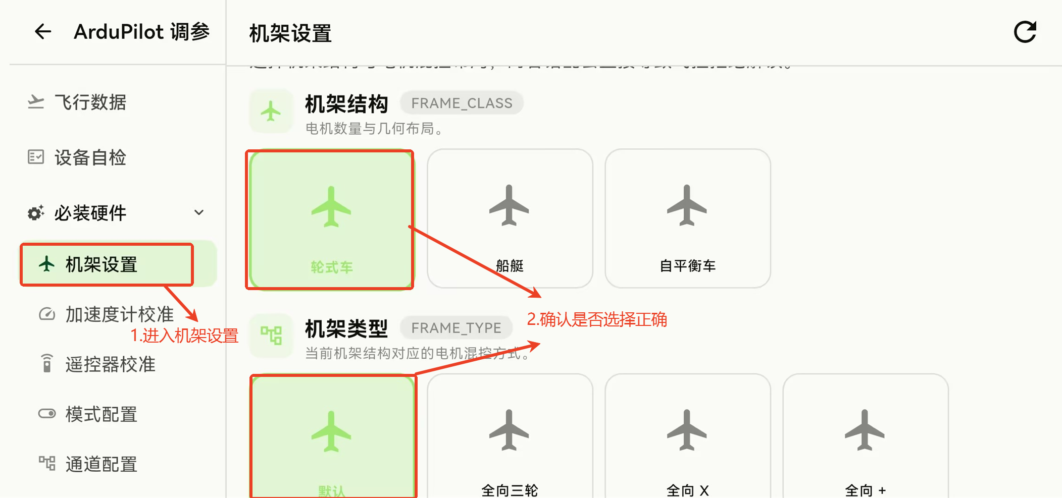
- Enter Frame Setup, confirm the frame structure is set to Wheeled Car, and the frame type is set to default
3.2 Accelerometer Calibration
Important
Note: When calibrating the accelerometer, be sure to remove the flight controller from the vehicle and place it on a flat surface for calibration. This improves accuracy and ensures correct vehicle attitude and heading estimation!
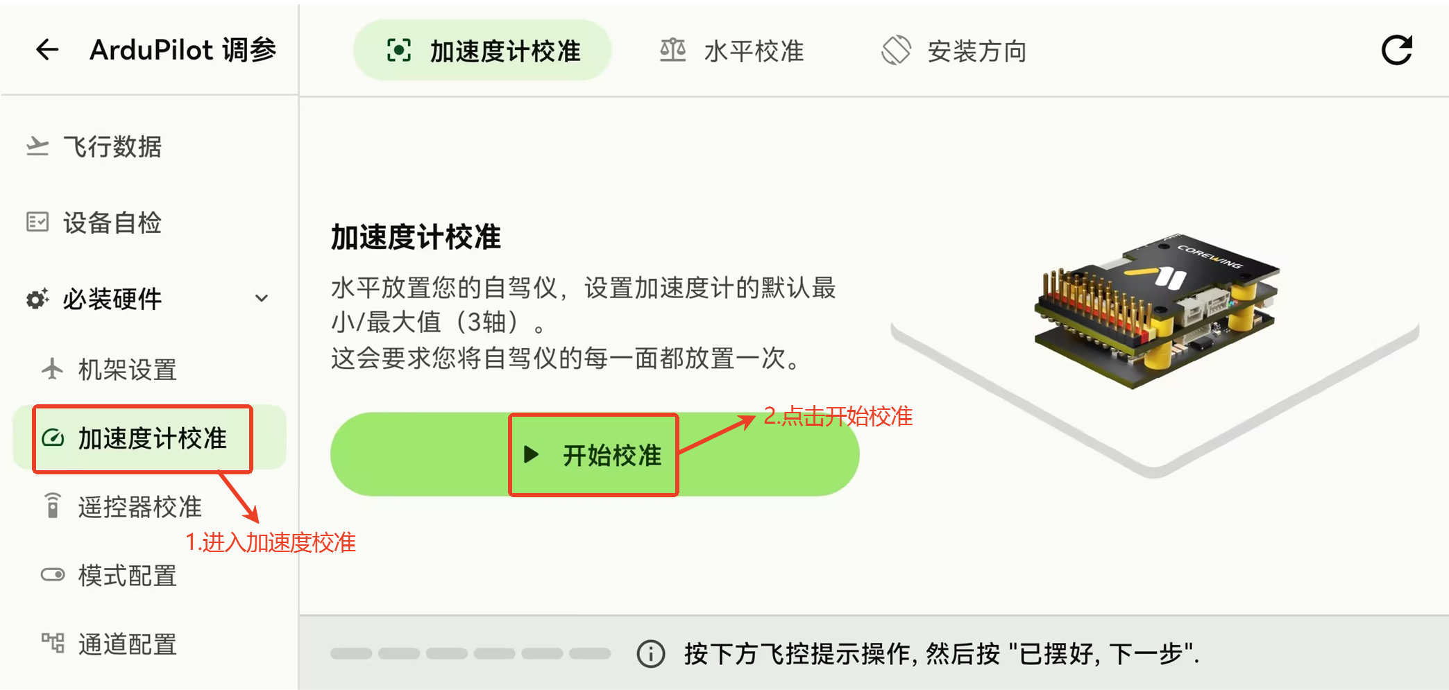
Click Required Hardware.
Click Accelerometer Calibration.
Click Start Calibration, place the flight controller as shown
3.3 Drive Mode Setup
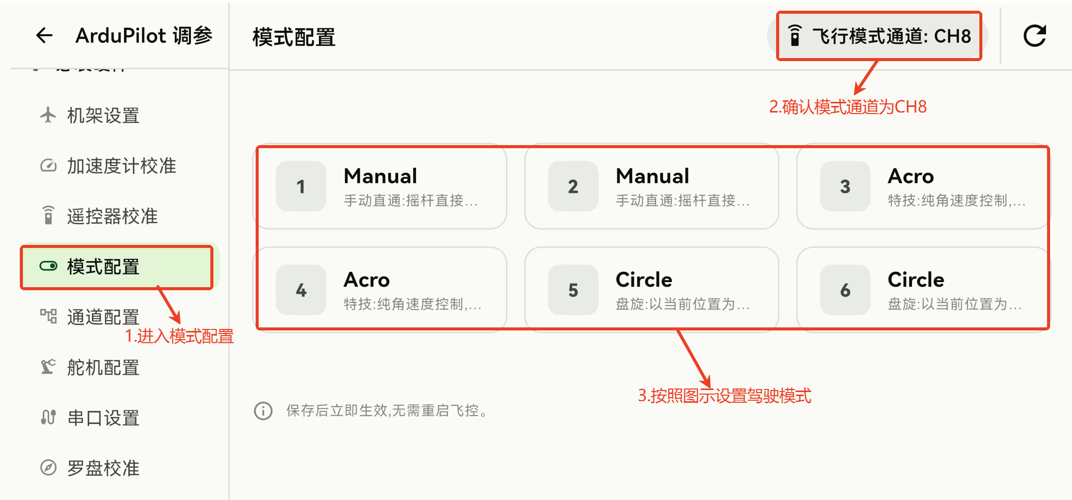
- Enter Mode Configuration and configure the Drive Modes as shown below
Mode Settings:
- Mode 1 and 2 set to Manual;
- Mode 3 and 4 set to Acro;
- Mode 5 and 6 set to Circle.
- After setup, click Write
3.4 Basic Settings
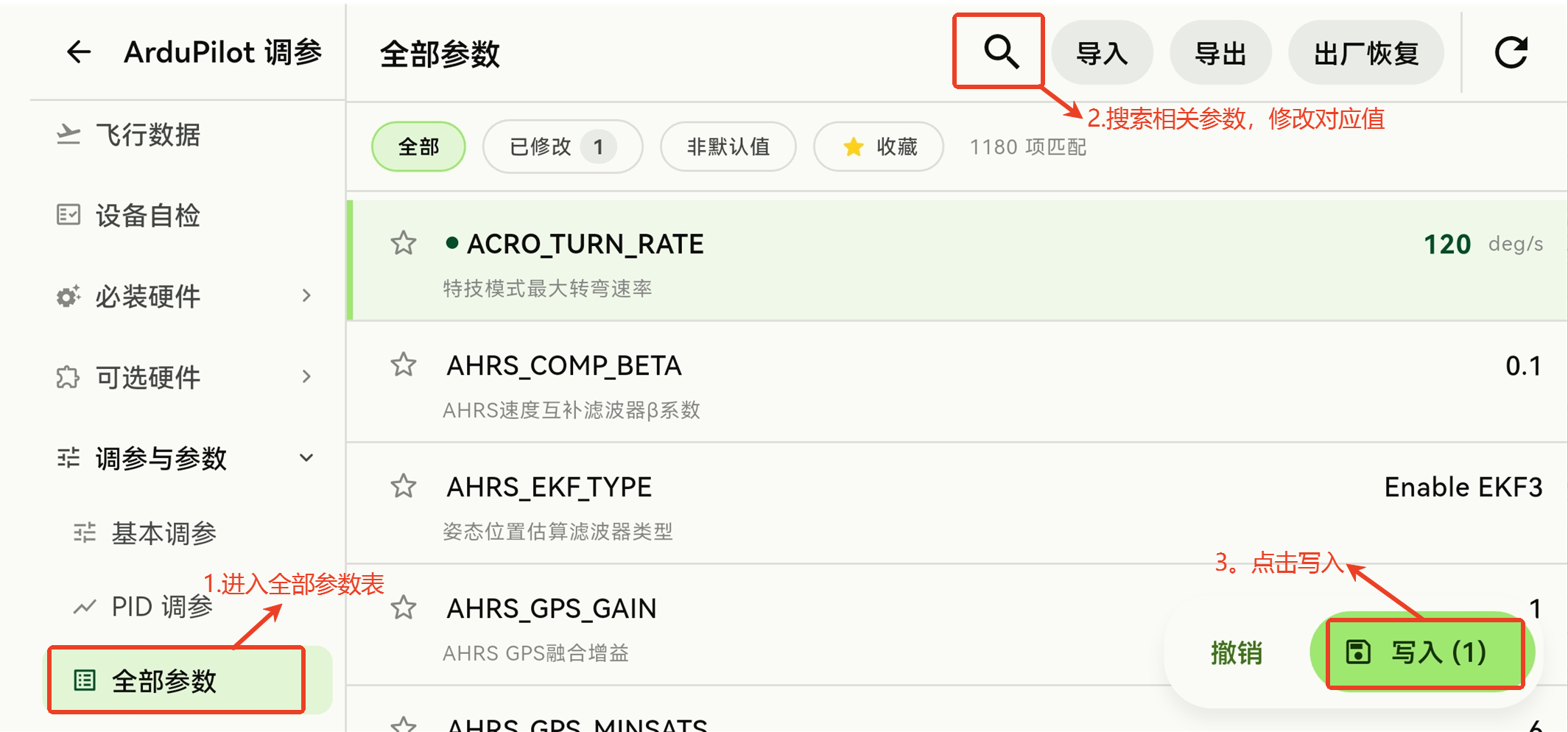
- Enter the Full Parameter List, search for the following parameters, configure them, and click Write
| Parameter Name | Value | Description |
|---|---|---|
| ACRO_TURN_RATE | 180 | Maximum allowed turn rate in Acro mode. |
| ATC_STR_ANG_P | 2 | Steering control loop P gain — converts the error between desired and actual steering rates into a desired steering rate |
| ATC_STR_ACC_MAX | 120 | Maximum steering angular acceleration; 120 is sufficient |
| ATC_STR_RAT_MAX | 120 | Maximum steering rate; 120 is sufficient |
| ATC_STR_RAT_P | 0.2 | Steering control loop P — converts the error between desired and actual speed into steering output |
| ATC_STR_RAT_I | 0.2 | Steering control loop I — compensates long-term error between desired and actual steering rates |
| ATC_STR_RAT_D | 0 | Steering control loop D — compensates short-term error between desired and actual steering rates |
| ATC_STR_RAT_FF | 0.2 | Steering control feedforward |
| CIRC_RADIUS | 1.5 | Target circle radius in Circle mode |